Blog

  • The Ultimate Kales Semi-Trailer Maintenance Manual & Service Guide

    The Ultimate Kales Semi-Trailer Maintenance Manual & Service Guide

    Published: October 30, 2025 | Last updated: May 30, 2026

    To ensure your Kales Vehicle semi-trailer operates safely, reliably, and cost-effectively, following a scientific and scheduled preventative maintenance program is non-negotiable. This comprehensive guide combines Kales Vehicle’s official OEM technical specifications with practical daily care tips, providing fleet managers and drivers with a master plan to proactively manage vehicle condition and eliminate safety risks.

    ⚠️ Important Safety Note: While this guide covers mechanical systems for Kales trailers, for ABS (Anti-lock Braking System) diagnostics, please refer strictly to the specialized ABS manufacturer’s manual.

    ℹ️ Kales Tech Tip: Regularly clean the ABS tone ring and sensor to remove mud or metal debris, which are the most common causes of ABS warning light errors on heavy-duty transport vehicles.

    🆕 CRITICAL: New Kales Trailer Break-In Protocol (First 5,000 km)

    During the first month of operation, metal components will “settle” and stretch. According to Kales Vehicle engineering standards, it is mandatory to perform the following checks after the initial loaded run-in period of approximately 5,000 km or one month:

    • 🔹 Axle Alignment: Re-measure and correct alignment as suspension settling can alter the wheelbase, affecting tire life.
    • 🟥 Suspension U-Bolts: Retorque to 600–650 N·m. Loose U-bolts are the #1 cause of leaf spring breakage in commercial trailers.
    • 🟥 Wheel Nuts: Retorque to 450–500 N·m to prevent wheel loss.

    Part 1: The Master Inspection & Maintenance Schedule

    Below is the complete Kales Vehicle Inspection Checklist. This schedule is strictly aligned with our factory technical manual to ensure your warranty remains valid and your trailer stays road-ready.

    💡 Inspection Legend:

    • Daily: Driver pre-trip check (Walk-around inspection).
    • 1 / 3 / 12 Month: Professional maintenance required by certified mechanics.
    • Condition: Most checks should be performed in the Towing State (connected to tractor) or Unloaded where specified.
    System Sub-System Check Items Dly 1M 3M 12M Judgement Standard & Remarks
    Brake Device Pneumatic Brake Hose & connector ✅ ✅ ✅ ✅ Replace if cracks/damage. Note: Replace hose every 2 years; reseal connector once a year.
    Air leakage ✅ ✅ ✅ ✅ Leakage is not allowed (In towing state).
    Brake chamber pushrod stroke ✅ ✅ ✅ Standard Type: 30–35mm (Limit: 50mm).
    Long Stroke Type: Refer to spec (Limit ~64mm).
    Function of emergency relay valve ✅ ✅ ✅ ✅ In normal operation.
    Function of brake chamber ✅ No crack, wear, damage. Replace rubber diaphragm every 2 years.
    Air pressure state ✅ Should be Normal (In towing state).
    Components Exhaust sound of emergency relay valve ✅ Should be Normal.
    Internal state of air reservoir ✅ ✅ ✅ ✅ No moisture (Drain water).
    Double safe brake mechanism ✅ ✅ ✅ Brake voluntarily when air pressure in inflating line drops to 0.4 MPa.
    Brake cam wear ✅ No overwear or damage.
    Clearance: Drum & friction plate ✅ ✅ ✅ Max clearance within 0.5–0.7mm. Adjust if exceeded.
    Brake shoe friction plate / Drum wear ✅ ✅ 1. Replace plate if rivet head lower than 1mm.
    2. Drum wear: Refer to axle instruction.
    Wheel Axle Axles Cracks, damage and distortion ✅ ✅ ✅ No cracks, damage or too big distortion.
    Tire pressure ✅ ✅ ✅ Refer to tire use requirements (kPa / psi).
    Wheels & Tires Wheel cracks and damage ✅ ✅ ✅ ✅ Replace when there is serious crack or damage.
    Tire depth / abnormal wear ✅ ✅ ✅ ✅ Tire depth shall not be less than 3mm.
    Metal piece/stone/foreign matters ✅ ✅ ✅ Remove completely.
    Tightness of wheel bolts & nuts ✅ ✅ ✅ ✅ Torque: 450 ~ 500 N·m
    Axle bearing swing (Wheel cross shake) ✅ ✅ Shall not be more than 3mm. Adjust if too large.
    Oil seal aging and damage ✅ Replace.
    Suspension Leaf Spring Deflection on Right vs Left ✅ Deflection difference shall not be too large. Adjust if needed.
    Damage / Cracks ✅ ✅ ✅ ✅ Replace if damage is serious or if crack exists.
    Connecting Parts U bolts & nuts ✅ ✅ Torque: 600 ~ 650 N·m
    Connecting rod shakes ✅ ✅ Pin & bush wear: Max clearance ≤1mm.
    Balance beam shakes ✅ ✅ Copper bush wear: Max clearance ≤0.5mm.
    Wearing surface of the leaf spring seat ✅ ✅ No overwear. Replace if necessary.
    Leaf spring offset ✅ ✅ No offset allowed.
    Legs Landing Gear Performance (Work function) ✅ ✅ ✅ ✅ In normal operation.
    Damaged inner/outer cylinders; Loose parts ✅ ✅ No crack, damage, or looseness.
    Wear on rotating/sliding parts ✅ No serious wear.
    Electric System Wiring Connecting parts loose/damaged; Crossover cable damage ✅ No looseness or damage.
    Lamp Device Function; Grimy points or damaged ✅ ✅ ✅ ✅ In normal work; No grimy points or damage.
    Other Device General King pin: Wear, crack or looseness ✅ ✅ ✅ ✅ No crack or looseness.
    Check verticality & neck wear.
    50# Limit: 48mm / 90# Limit: 86mm.
    Twist lock: Function ✅ Complete and in normal work.
    Reflector & license plate ✅ Normal (No grimy points/damage/install state).
    Frame & body (Welding parts) ✅ ✅ ✅ No deformation or large distortion. No cracks at welding parts.
    Spare wheel: Steady state ✅ ✅ ✅ ✅ Firm fixation.
    Unusual parts found in former running ✅ Check parts to see if there is abnormality.
    Lubricating parts: State ✅ ✅ In good state.

    🔩 Kales Vehicle Official Torque Specifications Cheat Sheet

    Use these Kales factory-recommended torque values to prevent mechanical failure. Save this section for quick access by your maintenance team.

    Component Torque (N·m) Kales Maintenance Notes
    Wheel Nuts 450 – 500 Check daily during break-in
    Suspension U-Bolts 600 – 650 Retorque after heavy loads
    Kingpin Locknut 1100 – 1300 For new or loose pins
    Hub Lock Nut 400 (Initial) ⚠️ Seating Torque ONLY! Must back off 1/8–1/6 turn.
    Brake Chamber Clamp 30 If leakage occurs

    Note: These specifications are proprietary to Kales Vehicle Co., Ltd. and ensure the optimal performance of Kales-manufactured trailers.

    Part 2: Comprehensive Kales Semi-Trailer Maintenance Steps

    Step 1. Brake System Maintenance: The Core of Safety

    Proper air brake maintenance is critical for heavy-duty trailer safety. Follow these Kales Vehicle diagnostic steps:

    • ✅ Connect the trailer’s air brake system to the tractor’s system.
    • ✅ Check all hoses and connectors for cracks, abrasions, or leaks. Replace immediately if damaged.
    • 📅 Maintenance Schedule: Replace all rubber air hoses every 2 years as per Kales safety recommendations.
    • ✅ Pressurize to operating level and verify pressure via tractor gauge or emergency system gauge (Normal: 0.7~0.8 MPa).
    • ✅ With engine idling, fully depress the brake pedal and hold. Pressure drop must not exceed 30 kPa per min.
    • 🧼 Leak Detection: If leakage is suspected, apply soapy water to fittings—bubbles >25 mm in 3 seconds indicate a leak. Tighten or replace as needed.
    • ⚙️ Check the emergency relay valve:
      a) Close the semi-trailer air supply line shut-off valve on the tractor, then disconnect the air coupling and check whether the brakes automatically apply. If they do not apply automatically, the emergency relay valve is faulty.
      b) Reconnect the air coupling between the tractor and the semi-trailer’s air supply line, then open the shut-off valve and check whether the brakes automatically release.
      c) Check all parts of the emergency relay valve for air leaks. If soap bubbles formed at any connection do not exceed 7 mm in diameter within 3 seconds, the valve is considered leak-free and functioning normally.
      d) When the brakes are released, verify that exhaust air is discharged from the exhaust port. If so, this indicates normal operation.e) If the valve operates sluggishly or fails to function properly, replace the entire emergency relay valve.

    ⚠️ WARNING: Critical Safety Notices

    Do Not Modify: Never modify the Kales brake air system, including adding water-spray brake cooling or tapping air from trailer tanks. This compromises braking performance and may cause catastrophic failure.

    ❄️ Winter Care: In cold weather, moisture in the brake system can freeze inside valves (relay/ABS), causing brake drag, delayed release, or total lock-up.

    • Mandatory: Drain water from all semi-trailer air tanks DAILY.
    • Check the Air Dryer desiccant cartridge efficiency and replace if saturated.
    • Always drain air tanks after driving. If excessive air loss affects brake function, re-pressurize.

    🔧 Brake Chamber Checks:a) While operating the brakes, check whether the pushrod of the brake chamber moves freely and whether its stroke is within the specified range (standard working stroke: 30–35 mm). If the stroke exceeds 50 mm, an adjustment is required. *Note: For Long Stroke (LS) chambers, the limit may be higher (~64mm). Verify the chamber type tag before adjusting.

    b) With the brakes applied, check the brake chamber for air leaks:

    • Apply soapy water to the clamp area and inspect for leaks. If leakage is detected, tighten the clamp retaining nut to a torque of 30 N·m.
    • Check the front vent hole for air leakage. If leaking, replace the rubber diaphragm.
    • Inspect the exterior of the brake chamber for cracks or damage. If any are found, replace the entire brake chamber as necessary using Kales genuine parts.

    🔧 Adjustment & Reservoir:Reservoir: Open drain valve daily to discharge condensate. Re-pressurize if emergency valve activates.

    Manual Adjustment:

    a) If stroke > 50mm, tighten worm shaft clockwise until seated.

    b) Back off 90-180 degrees.

    c) Depress pedal ~10 times to auto-adjust.

    d) Road Test: Ensure vehicle does not pull to one side.

    For detailed adjustment, refer to the axle manufacturer’s operating manual provided with your Kales trailer.

    Step 2. Axle & Hub Maintenance

    Ensuring your trailer axles are in top condition is key to longevity. Follow this hub bearing adjustment procedure carefully:

    • Inspect axles and tires for bends, cracks, or damage. Use a jack with support blocks when lifting.

    🔧 Hub Bearing Adjustment Protocol:

    1. Tighten inner hub nut to 400 N·m (to seat the bearing).
    2. Back off (loosen) 1/8 to 1/6 turn (ensure wheel rotates freely).
    3. Rotate hub—Rotate the hub and gently tap it with a hand hammer (at the hub bearing area) to check whether it turns freely. If the resistance is excessive, slightly loosen the locking nut until the hub can rotate freely on its own without noticeable wobble. Then install a cotter pin to secure the locking nut in place.
    4. Apply sealant to hub cap before installation.
    • Daily: Check wheel nut tightness. If loose, retorque to 450–500 N·m.

    Step 3. Tire Care: Maximize Life & Safety
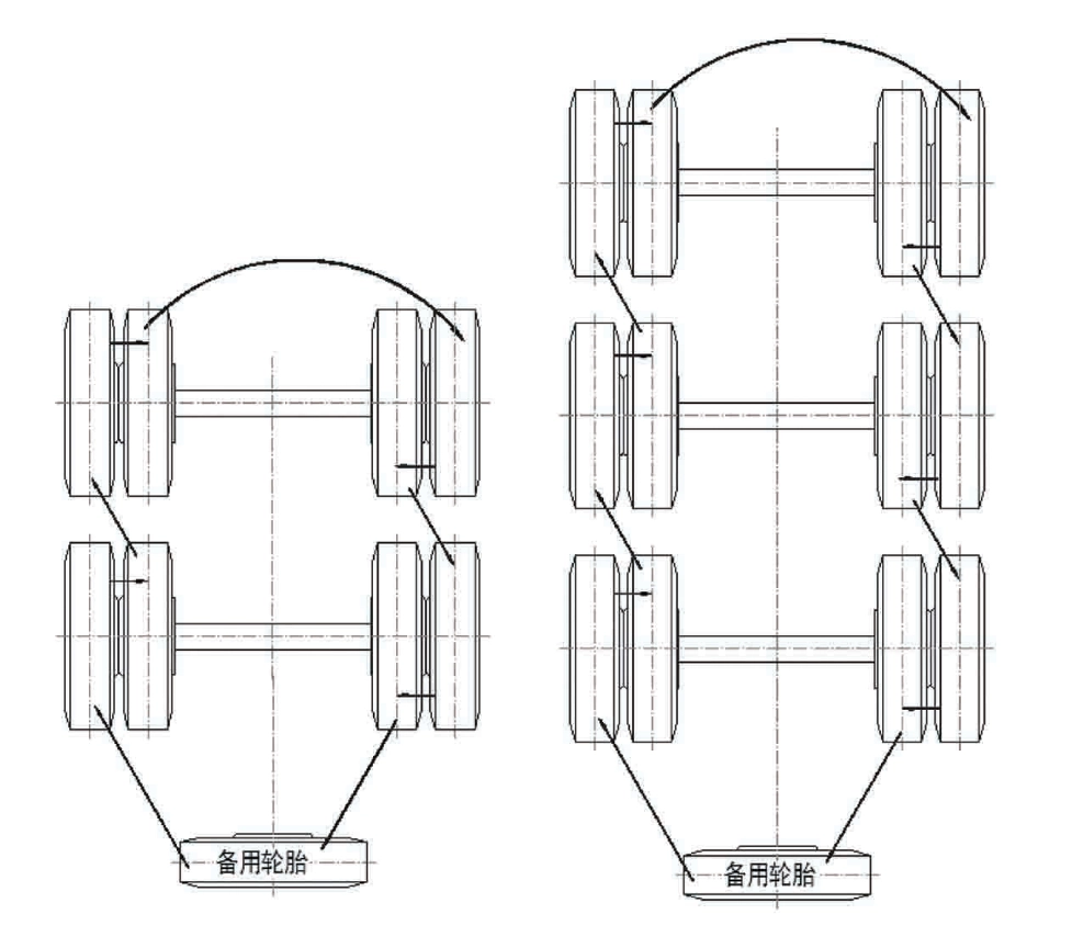
    Kales semi-trailer tire pressure check and maintenance guide for safety

    • 📉 Under-inflation: Causes shoulder wear, ply separation, blowouts, and higher fuel consumption.
    • 📈 Over-inflation: Accelerates center tread wear and increases risk of impact damage.
    • ✅ Maintenance: Maintain correct pressure (±20 kPa / ±3 psi) for all tires, including spares.
    • 🔄 Rotation: Tire wear varies depending on load, road conditions, and braking behavior. To promote even tire wear, tires should be rotated regularly—every 5,000 kilometers—following the sequence shown in the Kales tire rotation diagram above.
    • 🔧 Daily: The tightness of wheel nuts should be checked daily. If any looseness is found, the nuts must be retightened to a torque of 450–500 N·m.

    Step 4. Suspension System Maintenance

    A. Mechanical Suspension (Leaf Spring)

    • Daily: Check springs for breaks. If one side is damaged, replace both sides to maintain balance.
    • U-Bolts (Crucial):
      • Retorque to 600–650 N·m after heavy loads.
      • After replacing springs or every 5,000 km, inspect and retighten.
    • Bushings: Check connecting rod bushings—replace if cracked or worn (Limit: 1mm).

    B. Air Suspension

    • General Care: Avoid long-term parking. Drive a few km periodically to cycle air springs.
    • Cleaning: After muddy or asphalt roads, clean air springs and pistons. Replace if cracked, wrinkled, or abraded.
    • Every 6 months:
      • Inspect air dryer/filter—replace if clogged.
      • Check air line seals and valve tightness.
      • Verify U-bolt and air spring mounting bolt torque.
      • Drain air tanks (increase to every 2 weeks in freezing weather).
      • Verify ride height (H-value): Must match factory specification to ensure proper coupling and stability.
    • Every 3 months: Inspect shock absorbers for leaks or loose mounts.
    • Monthly: Check main beam bushings—no play should exist when rocking the trailer.

    Step 5. Landing Gear Maintenance

    • ✅ Check inner/outer tubes for smooth operation, deformation, or damage. Repair or replace as needed.
    • 🛢️ Lubrication: Inject grease into the gearbox and screw mechanism. Test high/low gears under no-load conditions to ensure smooth shifting. Use Kales-approved grease for optimal performance.

    Step 6. Kingpin & Fifth Wheel Maintenance

    The connection point between your tractor and Kales trailer requires diligent inspection:

    • ✅ Daily: Inspect kingpin for cracks, wear, or scoring.
    • 📏 Wear Limits: Replace if diameter < 48.0 mm (50#) or < 86.8 mm (90#).
    • 📐 Check Verticality: Replace if kingpin is bent, deformed, or shows uneven “neck” wear.
    • ✅ Clean and inspect fifth wheel plate—remove debris, check for warping.
    • ✅ Check the bolts of supporting seat and connection plate to see if they become loose, and if the supporting seat is damaged.
    • 🛢️ Lubrication: Lubricate kingpin and fifth wheel daily with high-quality grease (e.g., calcium-based ZG-4).

    🔎 Expert Checks:

    • For newly changed king pin or when the king pin becomes loose, tighten up the locknut of the king pin with tightening torque of 1100~1300 N·m.
    • Check the fifth wheel board to see if there is weld crack and if the wear plate is severely worn.
    • Check the lock hook, wearing ring and cross bolt to see if they are heavily damaged, deformed or become loose.
    • Check if the safety lock is in normal work, and whether the lever linkage is flexible or out of nimbleness.

    Step 7. Chassis Frame Inspection

    • Periodically inspect frame welds and main beams for cracks or distortion. Repair immediately if found. Kales Vehicle frames are built for durability, but regular checks ensure safety under heavy loads.

    Step 8. Axle Alignment & Wheelbase Adjustment

    Misalignment causes uneven tire wear and pulling. Check if U-bolts loosen or bushings wear.
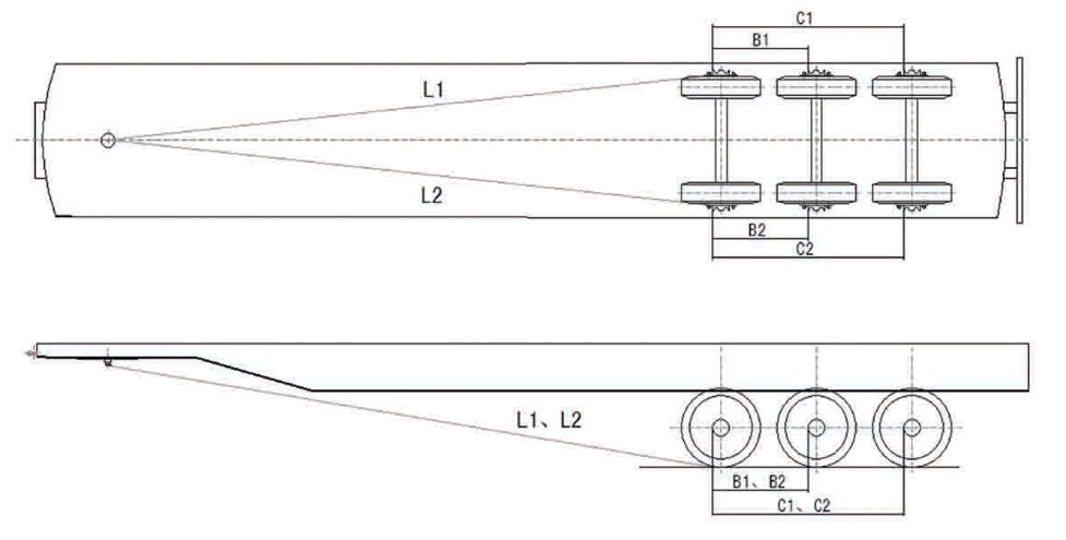
    Semi-trailer axle alignment and wheelbase adjustment diagram - Kales Vehicle Guide

    🔧 Adjustment Procedure:

    1. Park on level ground, uncouple tractor, release brakes. Adjust landing gear so front/rear frame heights match (±2 mm).
    2. Remove outer tires and dust caps. Drop plumb lines from hub centers to ground.
    3. Adjust the middle axle first: Adjust the movable tie rod so that the perpendicularity of the middle axle centerline to the longitudinal center plane of the chassis in the horizontal direction is ≤6 mm—i.e., L₁ = L₂ (measured as the distance from the kingpin center to the center holes of the hub caps (axle end covers) on both sides of the middle axle). After adjustment, tighten the set screws on the rod ends.
    4. Adjust the front axle: Adjust movable tie rod 1 to ensure the horizontal distance between the front and middle axles meets a tolerance of ≤5 mm—i.e., B₁ = B₂ (measured as the distance between the center holes of the hub caps (axle end covers) on both sides of the front and middle axles).
    5. Adjust the rear axle: Adjust the movable tie rod to ensure the horizontal distance between the rear and middle axles meets a tolerance of ≤5 mm (measured as the distance between the center holes of the hub caps (axle end covers) on both sides of the middle and rear axles).
    6. Tighten all bolts and nuts: Use box wrenches or socket wrenches to symmetrically tighten all fasteners to the specified torque values according to their specifications.

    Part 2.5: Regional Terrain Adjustments & Advanced Maintenance Guidelines

    Different operating environments place unique mechanical stresses on semi-trailers. According to Kales Vehicle engineering telemetry, maintenance protocols must be tailored to the geographical region of operation to ensure safety and prevent premature component failure.

    1. High-Altitude & Mountainous Terrain (e.g., The Andes Region)

    Operating in mountainous terrains like the Andes (covering countries such as Peru, Chile, Colombia, and Bolivia) demands special attention to brake thermal management and suspension stability:

    • Brake Thermal Monitoring: High-frequency brake applications on long descents (slopes > 6%) can push drum and disc temperatures beyond 400°C. Do not apply water spray to hot brake components, as the thermal shock will warp discs and crack drums. Allow components to cool naturally at designated rest stops.
    • Suspension Check Frequency: The continuous lateral force from winding mountain passes accelerates the wear of leaf spring plastic bushings and equalizer pins. Inspect the balance beam bushings and connecting rod pins every 3,000 km in these conditions.
    • Kingpin Structural Check: The constant pitch and roll of mountain driving put extreme stress on the kingpin. Inspect for hairline weld cracks at the supporting seat monthly.

    2. Arid, Dusty, & High-Temperature Environments (e.g., The Sahel Region)

    Transport corridors across the Sahel zone (stretching through Senegal, Mali, Burkina Faso, Niger, and Chad) present severe challenges regarding dust contamination and dry heat:

    • Dust Contamination & ABS Sensor Care: Fine Sahelian dust accumulates on the ABS tone rings and wheel speed sensors, leading to signal loss and dashboard warning lights. Sensors must be blown clean with compressed air weekly.
    • Lubricant Selection: Standard grease melts and runs out of hubs and landing gear gearboxes under extreme ambient temperatures (exceeding 45°C). Use only high-temperature lithium complex grease (with dropping point > 250°C) for all grease nipples and fifth-wheel plates.
    • Air Suspension Maintenance: Dust particles act as an abrasive on air spring bags (bellows). Wash the air suspension bellows weekly with fresh water (no detergents) to remove sand buildup and prevent micro-punctures.

    🔧 Advanced Torque Verification Table

    Maintain the following torque specs strictly under regional operation:

    Component Standard Torque Mountain/Rough Road Spec Verification Interval
    Wheel Nuts (Heavy-Duty Studs) 450 – 500 N·m 550 – 600 N·m Every 5,000 km (Daily during first 1,000 km)
    Suspension U-Bolts (M24) 600 – 650 N·m 650 – 700 N·m Every 10,000 km (After off-road hauling)
    Equalizer Shaft Nut 150 – 200 N·m 200 – 220 N·m Monthly service inspection

    Fleet Maintenance Evidence Loop: Inspect, Repair, Verify, Record

    A maintenance manual becomes useful only when every inspection creates a decision trail. For each trailer, keep a record that shows the driver check, the defect classification, the repair action, the final verification and the person who released the unit. This is especially important for fleets that run mixed routes, because brake heat, wheel-end looseness, dust ingress and chassis fatigue often appear after the trailer leaves the yard.

    Daily releaseUse the coupling and pre-trip guide to confirm fifth wheel lock, air lines, ABS lamps, lights, landing gear and wheel-end condition before dispatch.
    Brake and route riskTie brake adjustment, lining wear and air leaks to the ABS/EBS/RSS braking guide and the long downhill driving guide.
    Wheel-end and tiresRecord wheel nut retorque, hub seal condition, tire pressure and tread decisions. For lifecycle cost, compare casing condition with the semi-trailer tire retreading guide.
    Defect closureUse the troubleshooting guide to separate release-blocking faults from scheduled repairs, then close the record after pressure, torque, alignment or electrical verification.

    Safety reference basis: 49 CFR 396.3 maintenance records, 49 CFR 396.11 driver inspection reports, 49 CFR 396.17 periodic inspection, 49 CFR 392.7 pre-operation checks, and CVSA inspection levels.

    Part 3: Kales Technical Resources & Troubleshooting

    For detailed lubrication charts (grease types, specific points) and comprehensive troubleshooting guides (symptoms, causes, and solutions), please refer to our dedicated technical support pages:

    Semi-Trailer Maintenance FAQ

    What is the correct wheel nut torque for Kales trailers?

    Wheel nuts should be torqued to 450-500 Nm. During the first 5,000 km break-in period, check them daily or before every loaded dispatch, then keep them in the scheduled workshop torque record.

    How often should suspension U-bolts be checked?

    Retorque suspension U-bolts to 600-650 Nm after the first 5,000 km of loaded operation. Recheck them every 3 months, after severe routes, and after any suspension repair.

    Which defects should stop a semi-trailer from dispatch?

    Do not dispatch a trailer with air leakage, abnormal brake stroke, hot hubs, loose wheel nuts, cracked spring seats, severe tire damage, kingpin looseness, chassis cracks, or missing locking hardware. Repair and verify the defect before release.

    What records should a fleet keep for maintenance evidence?

    Keep inspection date, odometer or route, technician, torque or pressure readings, defect classification, repair action, replaced parts, verification result, and next service interval. This creates the evidence loop needed for warranty review and fleet audits.

    Conclusion

    By following this Kales semi-trailer maintenance manual, you protect your investment and ensure road safety. Regular maintenance according to these OEM standards is the best way to maximize the lifespan of your heavy-duty trailer.

    Need Technical Support or Genuine Kales Parts?

    Ensure your vehicle stays within warranty by using certified components. Our engineering support team is available 24/7 to assist with maintenance questions, parts ordering, and custom fleet configurations.


    Need help applying this guide?

    Share your trailer type, payload, routes, operating climate, and photos with Kales. Our team can review the key points from this guide and recommend a practical specification for your fleet.

    1. Send photos of your tractor, trailer, or current component layout
    2. Confirm payload, road conditions, gradients, climate, and duty cycle
    3. Receive a specification or maintenance recommendation within 24 business hours

    Email: jennylee@kalestruck.com  |  WhatsApp: +86 131 5638 8843  |  Request a quote

  • How to Couple a Semi-Trailer: The Complete Step-by-Step Guide

    How to Couple a Semi-Trailer: The Complete Step-by-Step Guide

    Published: October 30, 2025 | Last updated: May 30, 2026

    Lead Fleet Maintenance Engineer at Kales

    Reviewed by Jason M.

    Lead Fleet Maintenance Engineer, Kales Vehicle

    What is a semi-trailer pre-trip inspection and coupling procedure? A semi-trailer pre-trip inspection is a mandatory safety protocol involving the visual and mechanical verification of the fifth-wheel coupling, air brake system pressure (800-850 kPa), and wheel nut torque (600-650 N.m). Proper execution of these steps, in accordance with commercial driving regulations, prevents trailer detachment, load loss, and severe highway accidents.

    Key takeaways before coupling

    • A safe semi-trailer coupling is not confirmed by a click sound alone; it requires a visual fifth wheel jaw check, a controlled tug test, connected air and electrical lines, and a brake response test.
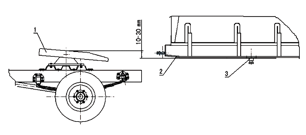
    • The kingpin plate should sit 10-30 mm lower than the fifth wheel before backing under the trailer, so the tractor lifts the trailer slightly and prevents a false lock.
    • Any hissing air line, ABS warning lamp, damaged gladhand seal, cracked landing gear pad, missing wheel nut or unverified retorque is a no-go defect until corrected.
    • For new trailers, the first loaded trip is part of commissioning: wheel nuts, suspension U-bolts and air fittings need a documented recheck after the initial 50-100 km.

    ⚠️ DANGER / WARNING

    Always park the tractor and semi-trailer on a level, firm surface and engage the parking brakes before attempting to couple or uncouple. Failure to visually verify that the fifth wheel jaws securely lock around the kingpin can result in trailer detachment, load loss, and severe accidents. Chock the trailer wheels before reversing.

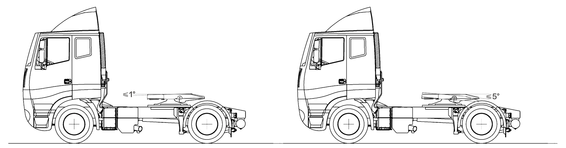
    Correct front to rear tilt angle of the fifth wheel for semi-trailers
    Figure 1: Ensure the correct front-to-rear tilt angle of the fifth wheel before attempting to couple the trailer.

    The “Emergency Room” Matrix

    Symptom Possible Root Cause Immediate Solution
    The fifth wheel jaws fail to lock around the semi-trailer kingpin. The trailer kingpin plate is resting too high relative to the tractor fifth wheel. Lower the landing gear so the kingpin plate sits 10 to 30 millimeters below the center of the fifth wheel.
    A loud hissing noise comes from the air line connections at the front of the trailer. The rubber seals inside the red or yellow gladhands are damaged, or dirt is blocking the connection port. Disconnect the gladhands, clean off any debris, and replace the rubber seals if they show signs of cracking.
    The trailer ABS warning light stays illuminated on the dashboard. The 7-pin electrical plug or the dedicated ISO ABS cable is not fully inserted into the tractor socket. Push the electrical cables firmly into their respective sockets and ensure the locking caps snap fully shut over them.
    Your new trailer exhibits loose wheel nuts shortly after beginning its first commercial haul. The new steel rims, studs, and paint layers naturally settle and compress during their initial period under heavy load. Retorque every wheel nut to the specified 600 to 650 N.m using a calibrated heavy-duty torque wrench.

    Critical Specs & Torque Settings

    • Wheel Nut Torque Requirement: 600 – 650 N.m
    • Initial Retorque Interval: First 50 – 100 km (30 – 60 miles) of loaded driving
    • Air Brake System Operating Pressure: 800 – 850 kPa (116 – 123 psi)
    • Optimal Coupling Height Difference: Kingpin plate 10 – 30 mm lower than fifth wheel center
    • Maximum Articulation Angle for Coupling: 5 degrees or less
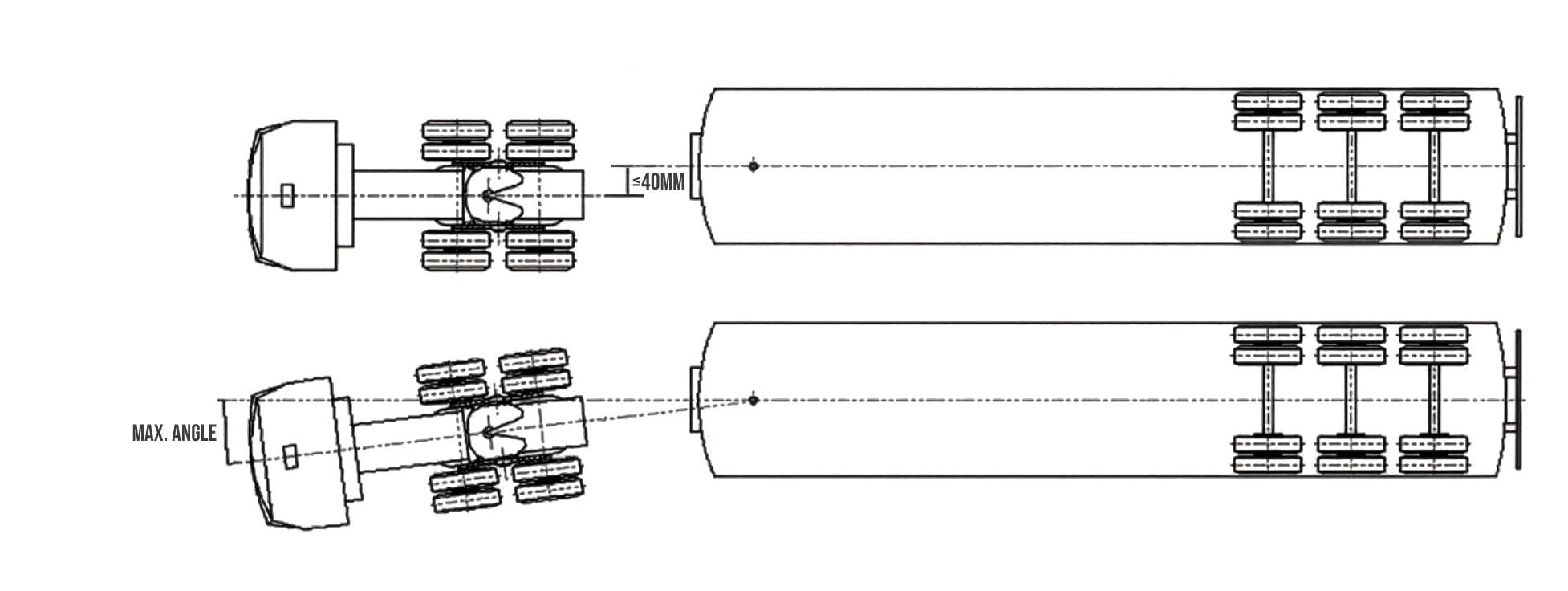
    • Coupling Centerline Tolerance: Within 40 mm
    📈 Field Experience Note:

    In our experience servicing thousands of commercial fleets, failure to perform the mandatory 50km wheel nut retorque procedure is the number one cause of hub damage and catastrophic wheel-off incidents on brand-new trailers. Never skip this initial maintenance step.

    Step-by-Step Coupling Guide

    Diagram showing proper height difference between fifth wheel and kingpin plate
    Figure 2: The kingpin plate must sit slightly lower than the fifth wheel.

    Step 1: Adjust Landing Gear

    Crank the landing gear handle to raise or lower the trailer. Set the height so the kingpin plate sits exactly 10 to 30 millimeters lower than the center of the tractor’s fifth wheel. This allows the tractor chassis to physically lift the trailer slightly during engagement.

    Tractor to Semi-Trailer Articulation Angle Limit
    Figure 3: Keep articulation angles under 5 degrees for a safe coupling.

    Step 2: Align the Tractor

    Open the locking jaw mechanism on the fifth wheel. Reverse the tractor slowly, keeping the trailer and tractor centerlines within a 40-millimeter tolerance. Keep the tractor articulation angle equal to or less than 5 degrees to avoid damaging the kingpin.

    Step 3: Lock & Visually Inspect

    Reverse the tractor until the kingpin slides in and locks automatically into the fifth wheel. Exit the cab and shine a flashlight directly under the fifth wheel to visually confirm the jaws are entirely closed around the kingpin shank. Never rely solely on the sound of the latch or an in-cab tug test.

    Step 4: Connect Pneumatics & Electrical

    Attach the red gladhand to the supply line. Attach the yellow gladhand to the control line. Plug the 7-pin and ISO cables into the receptacles. Open the fast-fill supply valve to build the system pressure to at least 800 kPa, in accordance with commercial driver handbook combination-vehicle guidance.

    Go / no-go checks before leaving the yard

    Use the coupling procedure as a release gate, not just a routine. Under commercial vehicle rules, drivers must be satisfied that key parts and accessories are in good working order before operation and must review inspection reports when defects were previously noted. In practical fleet work, that means the driver and dispatcher should both know which defects stop the truck immediately.

    • Fifth wheel and kingpin: go only when the jaws are fully closed around the kingpin shank, the release handle is seated and there is no visible gap. Stop for a high-riding kingpin, loose handle, missing safety clip or metal cracking.
    • Air lines and gladhands: go only when red and yellow lines are connected, seals are clean and no audible leak appears while pressure builds. Stop for hissing, crossed lines, damaged seals or pressure that cannot recover.
    • Electrical and ABS: go only when the 7-pin plug, ABS/ISO line, brake lamps and turn signals are confirmed. Stop for an ABS lamp that stays on, intermittent lights, corrosion or damaged cable insulation.
    • Landing gear: go only when the legs are fully raised, crank secured and pads undamaged. Stop for a bent leg, cracked foot pad, stuck gearbox or incomplete retraction.
    • Wheel end: go only when all wheel nuts are present, hub seals are dry and first-trip retorque is recorded. Stop for a missing nut, fresh rust trail, oil leak or abnormal tire bulge.

    Preventative Maintenance Checklist

    • Pre-Trip: Inspect all red and yellow gladhands to ensure the rubber seals are clean and intact.
    • Pre-Trip: Test all brake, turn, and clearance lights to confirm they illuminate brightly.
    • Pre-Trip: Build air pressure to 850 kPa and listen carefully around the axles for any hissing sounds indicating air leaks.
    • Post-Delivery (New Trailers): Retorque all the wheel nuts to 600-650 N.m after driving the first 50-100 kilometers under load.
    • Weekly: Verify that all suspension U-bolts and axle plates remain tight and free from metal fatigue cracks.
    • Weekly: Examine tire pressures and tread depths across all axles.

    Need Spare Parts?

    We stock all Kales Vehicle original parts, including heavy-duty gladhands, 7-pin electrical cords, ABS sensors, and replacement wheel studs. Consult the exploded view diagrams in your owner’s manual to find the exact Part Number you require.

    Yard Release Log: Turning Coupling Into a Signed Safety Control

    For fleets, the coupling task should end with a short release log, not only a driver memory check. Record the trailer number, tractor number, kingpin lock confirmation, air-pressure build, ABS lamp behavior, light test, landing gear position and wheel-end condition before the unit leaves the gate. This creates a practical evidence trail if a brake, electrical or wheel-end fault appears during the first shift.

    A dispatch note also helps mixed fleets: when tractors rotate between flatbeds, lowbeds and tankers, the next driver can see whether fifth wheel height, air-line routing or wheel retorque already required attention on the previous trip.

    Geometry checkIf the tractor ride height, fifth wheel position or kingpin approach angle is wrong, the driver may high-hook or damage the apron. Use the tractor-trailer matching guide when assigning tractors across mixed trailers.
    Lubrication and wearDry fifth wheel plates, seized landing gear and worn pins turn a normal coupling into a failure point. Add fifth wheel plate, landing gear and suspension grease checks to the semi-trailer lubrication routine.
    Brake and electrical releaseThe vehicle should not move until service and emergency air lines are sealed, pressure builds normally, the ABS lamp cycle is understood and all lights work. 49 CFR 392.7 and 396.13 are useful references for pre-operation and driver report responsibilities.
    No-go defect ruleDo not dispatch with uncertain fifth wheel lock, air leakage, damaged gladhands, missing wheel hardware, bent landing gear or exposed wiring. These are release-blocking defects, not notes for the next service interval.

    Related KALES guides and trailer choices

    Coupling safety is connected to brake condition, tire condition, fifth wheel geometry and trailer configuration. Use these related pages when training drivers or specifying a new trailer for mixed fleet work.

    Sources used for safety context

    Frequently Asked Questions

    Why did my semi-trailer wheel come loose during the first trip?

    New rims and studs naturally settle during initial loaded use, which reduces wheel nut clamping force. Retorque all wheel nuts to 600-650 N.m after the first 50 to 100 kilometers of loaded driving and record the result before the trailer continues long-haul work.

    What is the correct height for coupling a semi-trailer to a tractor?

    The trailer kingpin plate should sit 10 to 30 mm lower than the center of the tractor fifth wheel. This lets the tractor lift the trailer slightly during engagement and helps the fifth wheel jaws close securely around the kingpin.

    How do I reliably test the air brake system during a pre-trip inspection?

    Build pressure to 800-850 kPa, listen around axles and gladhands for air leakage, then apply the service brake and confirm that all trailer wheels respond together. Do not dispatch if pressure drops abnormally or a chamber, hose, or coupling leaks.

    Which coupling defects are no-go items before yard release?

    Stop dispatch for an unlocked fifth wheel, visible gap between upper plate and fifth wheel, damaged kingpin, leaking gladhands, ABS lamp fault, unretracted landing gear, loose wheel nuts, missing safety locks, or any brake pressure failure. Record the defect and verify repair before release.

    Stuck? Let our Engineers Help.

    Experiencing persistent coupling issues or air leaks? Send us a photo or video of the affected component.

    Need help applying this guide?

    Share your trailer type, payload, routes, operating climate, and photos with Kales. Our team can review the key points from this guide and recommend a practical specification for your fleet.

    1. Send photos of your tractor, trailer, or current component layout
    2. Confirm payload, road conditions, gradients, climate, and duty cycle
    3. Receive a specification or maintenance recommendation within 24 business hours

    Email: jennylee@kalestruck.com  |  WhatsApp: +86 131 5638 8843  |  Request a quote
  • Manufacturing Kales Bulk Powder Tankers: Precision Engineering for Cement & Fly Ash Trailers

    Manufacturing Kales Bulk Powder Tankers: Precision Engineering for Cement & Fly Ash Trailers

    Published: October 27, 2025 | Last updated: May 30, 2026

    Lead Structural Engineer at Kales

    Reviewed by Jason M.
    Chief Structural Engineer, Kales Vehicle

    💡 Executive Key Takeaways:

    • Discharge Speed: High-performance Kales fluidized bed achieves rapid unloading rates of 1.2 to 1.5 tons/minute.
    • Minimal Waste: The V-shaped tank design and “No-Dead-Corner” geometry guarantee a residual rate of less than 0.3%.
    • Powertrain Quality: Equipped with a Weichai 4102 auxiliary diesel engine and a Bohai 12m³ double-cylinder air compressor for stable 0.2 MPa operating pressures.

    What is a pneumatic dry bulk trailer? A pneumatic dry bulk trailer (also known as a cement bulker or bulk cement tanker) is a specialized heavy-duty commercial vehicle designed to transport dry powder materials with a particle size of ≤ 0.1mm, such as bulk cement, fly ash, lime, mineral powder, and flour. Achieving fast discharge speeds and structural durability requires precision engineering, including CAE design, T700 high-strength steel, and robotic welding.

    About Kales Vehicle: A Premier Powder Tanker Manufacturer

    Founded in 2012 and headquartered in Shandong, China, Kales Vehicle possesses over a decade of specialized experience in semi-trailer R&D and manufacturing according to ISO 9001 quality management standards. We have successfully delivered 12,000+ units globally, including over 2,000 pneumatic dry bulk trailers, serving heavy industry clients across East Asia, Southeast Asia, Central Asia, the Middle East, and Africa.

    We don’t settle for “good enough.” We build heavy-duty transport equipment engineered to withstand the toughest job site conditions.

    Why High-Quality Cement Bulkers Are Difficult to Perfect

    A common misconception in the logistics industry is that a powder tanker is simply “a steel tank welded onto a chassis.” In reality, achieving fast discharge speeds, minimal residue rates, stable handling, and long-term chassis durability depends entirely on precision engineering. A poorly built tanker inevitably leads to clogged pipes, structural cracks, and severe profit loss.

    Follow us as we walk you through the 7-step manufacturing journey of a premium Kales bulk powder transport trailer.

    🔧 Step 1: Design – CAE Simulation for Maximum Structural Integrity

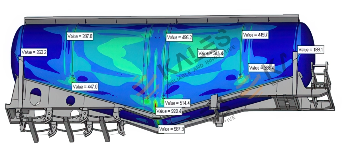
    3D CAE Simulation model of Kales Cement Bulker Trailer
    Figure 1: Advanced 3D CAE Simulation validates structural integrity before physical production.

    We do not rely on empirical estimates; instead, we utilize advanced 3D modeling and CAE (Computer-Aided Engineering) mechanical simulations to validate every structural component before production begins.

    • We utilize a steeper tank angle design that exceeds standard industry benchmarks by 2–3° to ensure smoother material flow and significantly faster discharge rates.
    • We rely on rigorous stress analysis to inform the skeletal layout, effectively preventing cracking and deformation under heavy payloads.
    • We engineer a refined chassis structure that deliberately lowers the center of gravity (C.G.), providing superior anti-rollover stability on rough mining terrain.

    ✂️ Step 2: CNC Cutting & Forming – Precision Defines Lifespan

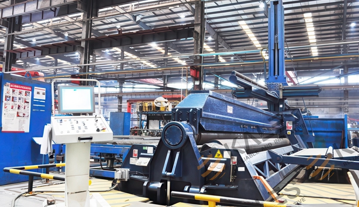
    CNC Plate Rolling Machine forming tank body steel
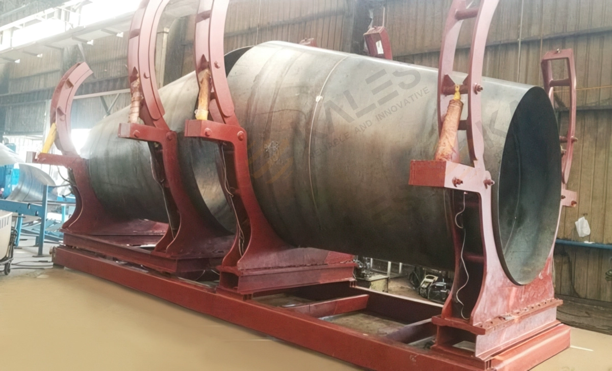
    Frame alignment jig for powder tanker assembly
    • We strictly utilize premium T700/Q345B high-strength steel that is laser-cut to a strict tolerance of ≤ 0.01mm to maintain 100% material integrity.
    • We process the tank body using advanced CNC rolling machines in a single pass, completely eliminating the hammering and internal stress that cause structural weak points.
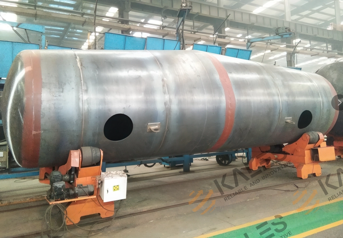
    • We assemble the sections on a framed assembly platform to guarantee a perfectly straight and true tank body alignment.
    💡 Engineering Insight: Any thermal warping or internal damage to the steel during the forming process drastically increases the risk of future weld seam cracking under pressure.

    🔥 Step 3: Robotic Welding – The Invisible Craftsmanship

    Automatic Robotic Welding Process for Kales Tanker Trailers
    Figure 2: Automated robotic welding ensures uniform, deep-penetration seams for pressure vessel safety.

    We utilize fully automated robotic welding technology to ensure the tank can safely withstand high internal pneumatic pressure without failure. For the longitudinal and circumferential seams of the pressure tank, we implement single-sided welding with double-sided forming technology. This method utilizes TIG/MIG backing followed by automated submerged arc welding, creating a deep-penetration, defect-free joint that meets rigorous X-ray inspection standards.

    • We deploy single-sided welding with double-sided forming technology to create deep, consistent penetration for maximum seam strength.
    • We ensure all welds are flawlessly uniform and completely free of porosity, undercut, or slag inclusions, which is critical for pressure vessel safety standards.
    • We guarantee even stress distribution across the entire tank body to prevent localized stress points that lead to metal fatigue over time.

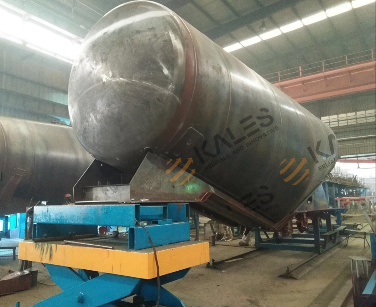
    ⚙️ Step 4: Chassis Alignment – Eliminating Trailer Sway

    Chassis Frame Leveling and Alignment System
    Figure 3: Precision chassis alignment prevents irregular tire wear and trailer swaying.

    A frequent driver complaint with inferior trailers is a dangerous “swaying” or “wobbling” sensation at highway speeds. Kales resolves this by performing meticulous chassis and kingpin laser alignment immediately after the tank is mounted.

    💨 Step 5: The “Heart” of the System – Air Compressor & Discharge

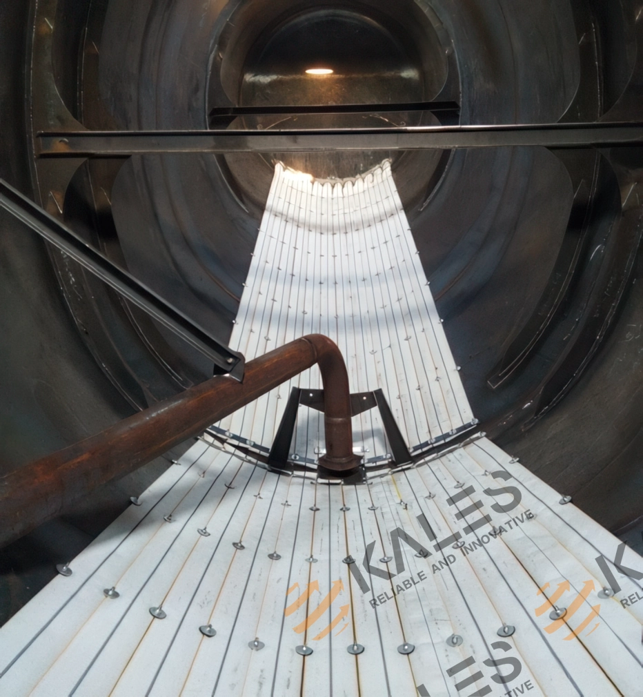
    Internal Fluidization Bed of Kales Powder Tanker
    Detailed schematic of Kales Cement Bulker discharge system

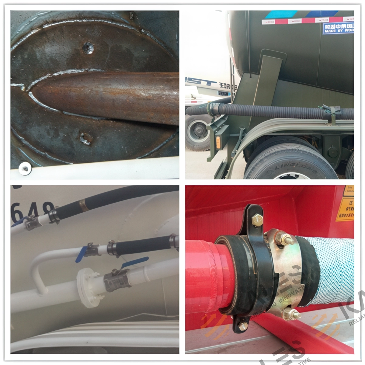
    The operational efficiency of a pneumatic trailer relies entirely on its power source and internal fluidization design. The core of this system is the auxiliary powertrain, consisting of a heavy-duty Weichai 4102 diesel engine (developing 44 kW / 60 HP) paired with a Bohai 12m³ double-cylinder rotary air compressor. Operating at a stable speed of 900–1000 RPM, this compressor delivers a steady flow of compressed air to pressurize the tank to a working pressure of 0.2 MPa (2 bar). High volumetric efficiency is key to maintaining consistent air volume and preventing pressure drop during unloading.

    • We equip our trailers with renowned Weichai Diesel Engines and Bohai/Fuda Air Compressors (12m³ double-cylinder) to ensure a massive and stable air pressure output.
    • We combine an enlarged outlet with a high-angle fluidized bed to achieve remarkable discharge speeds of up to 1.5 tons per minute.
    • We implement a “No-Dead-Corner” internal tank structure to guarantee a residual rate of <0.3%, ensuring you deliver more product on every load.
    📈 Real Field Experience: In 2024, a major cement logistics client in the Middle East reported that our optimized fluidized bed design reduced their per-truck discharge time by 12 minutes, directly saving thousands of liters in diesel fuel annually across their fleet.

    🎨 Step 6: Protective Coating – Marine-Grade Protection

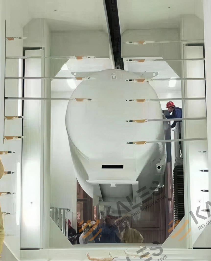
    Polyurethane Painting Process for Kales Tankers

    To protect the tanker body from mechanical abrasion and chemical corrosion, we perform automated steel shot blasting to Sa 2.5 cleanliness standards before applying coatings. We then apply an electrostatic Polyurethane Powder Coating. The final dry film thickness (DFT) reaches an H-grade marine standard of 120μm+, forming a highly durable barrier that prevents under-film corrosion and chalking in high-humidity climates.

    • We apply an environmentally friendly, phosphate-free, and heavy-metal-free Polyurethane Powder Coating.
    • We ensure our coating thickness reaches H-Grade (Marine Standard) at 120μm+, providing superior resistance to salt spray and humidity.
    • We guarantee our paint finish is proven to withstand 5–8 years without fading or peeling, even in harsh tropical climates.

    🔍 Step 7: Quality Control – Rigorous Pressure Testing

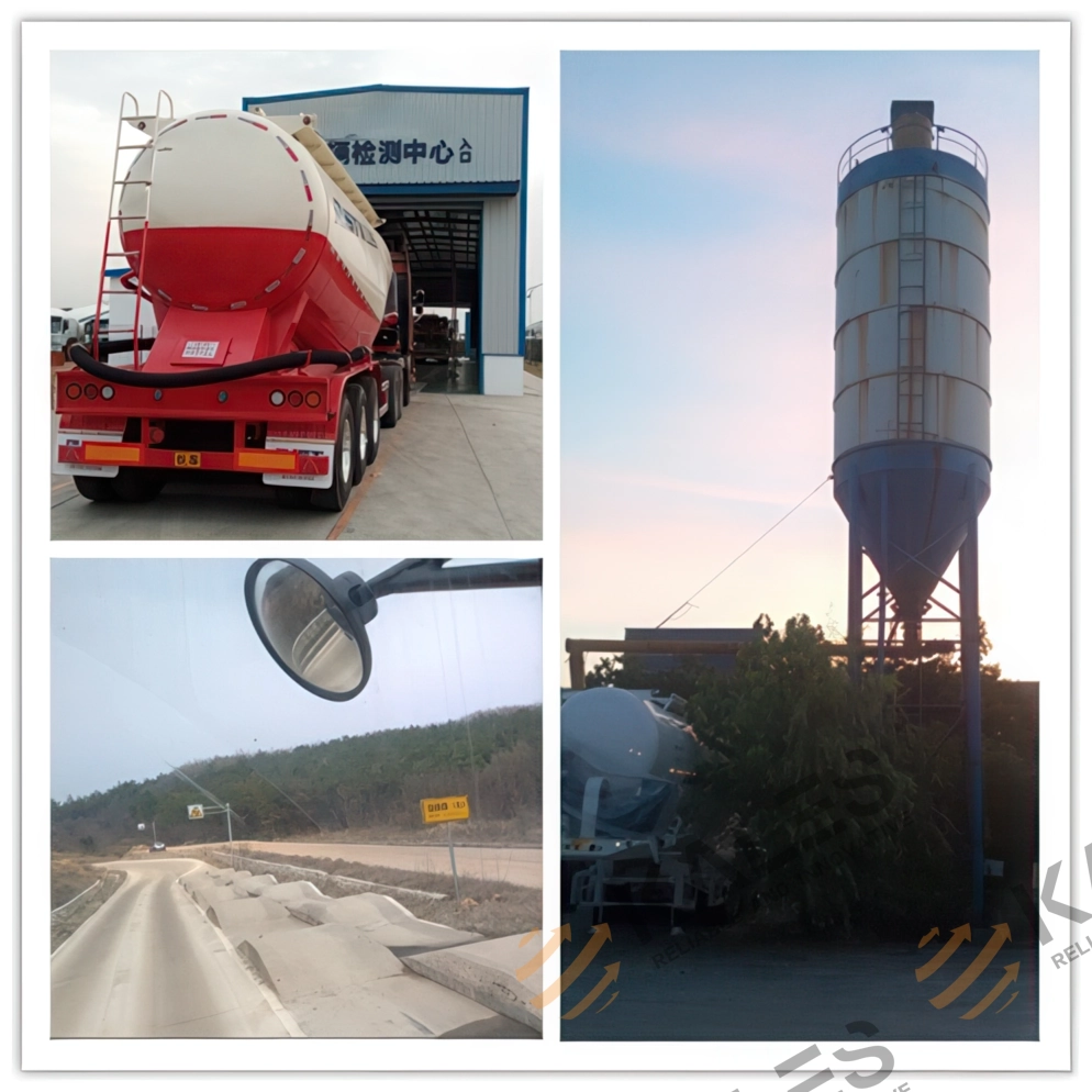
    Kales Vehicle Quality Control and Testing Center

    Every cement bulker trailer must pass a rigorous QC inspection before shipping:

    • We conduct strict Air Tightness Tests using high pressure to ensure absolutely zero pneumatic leaks.
    • We perform Discharge Efficiency Tests to manually verify unloading speeds and residue rates.
    • We execute 30 km/h Cornering Stability Tests on the testing track to ensure anti-rollover safety for the driver.

    If it doesn’t pass, it doesn’t ship. Period.

    Manufacturing QA Gate: What Buyers Should Verify Before Shipment

    A bulk powder tanker can look perfect from the outside while still losing money through slow discharge, hidden weld fatigue or coating failure. For export fleets moving cement, fly ash or mineral powder across African highways, mines and port corridors, the practical inspection point is the manufacturing record: steel batch, weld control, pressure tightness and unloading residue. These checks convert a factory tour into evidence that the trailer will hold up after thousands of vibration cycles.

    Shipment evidence packet

    Before a powder tanker leaves the factory, the buyer should receive a compact evidence packet: tank material traceability, weld and alignment checkpoints, coating record, pressure tightness result, discharge or residue test note, compressor model, hose and valve list, and the first spare-parts recommendation. This does not replace the buyer’s own inspection, but it gives the fleet a factual baseline for warranty review, port acceptance and later maintenance decisions.

    For handover, request a compact factory QA packet: material list, welding and alignment checkpoints, coating notes, pressure-test result, discharge-test result and spare-part list. This packet helps the fleet compare the delivered trailer with the quotation before the unit leaves the yard.

    1. Material traceabilityAsk whether the tank shell, chassis beam and reinforcement plates are traced by batch and thickness. Buyers comparing T700, Q355 or other HSLA steels should also review the related semi-trailer chassis material guide.
    2. Weld and fit-up controlLong seam welds, ring stiffeners and landing gear brackets deserve visual inspection and dimensional checks. Structural welding references such as AWS D1.1 and ISO 3834 are useful vocabulary for discussing weld quality, even when a buyer uses project-specific acceptance criteria.
    3. Pneumatic discharge proofA realistic discharge test should verify pressure stability, cloth fluidization, outlet flow and residue. Use the bulk powder tanker operation guide to connect factory test results with driver procedures.
    4. Coating and service accessPaint film thickness, blasting cleanliness, ladder access, air-line routing and grease point access affect maintenance cost. Compare the coating process with the semi-trailer anticorrosion process guide.

    Related Engineering Resources and Source Basis

    For E-E-A-T review, this manufacturing article should be read together with operation, maintenance and material pages rather than as a stand-alone brochure. A buyer building a tender for a cement bulker, pneumatic dry bulk trailer or fly ash tanker can use the linked pages to check specifications after delivery.

    External reference basis: ASTM A572/A572M for HSLA structural steel terminology, AWS D1.1 for structural welding vocabulary, ISO 3834 for welding quality requirements, and OSHA 1910.242 for compressed-air safety awareness.

    Summary: What Defines a Superior Bulk Powder Tanker?

    Performance Metric The Kales Engineering Solution
    Fast Discharge Speed High-angle tank + Bohai Compressor + optimized fluidized bed.
    Low Residue Rate (<0.3%) “No-dead-corner” internal structure + precision airflow mechanics.
    Long-Term Durability T700 High-strength steel + automated robotic welding + CAE.
    📌 Operational Variables & Transparency:
    While Kales pneumatic trailers are engineered for a discharge speed of up to 1.5 tons per minute, actual unloading efficiency is highly dependent on the density, humidity, and particle size of the specific dry bulk material being transported, as well as the skill of the compressor operator.

    What a Buyer Should See in the Factory Acceptance Record

    A credible pneumatic tanker build should end with a record pack, not only a finished trailer photo. For export buyers, Kales normally treats the record as evidence that the tanker was manufactured from traceable high-strength steel, welded under a controlled procedure, aligned before coating, and checked for air tightness before shipment. This matters because a powder tanker is both a pressure-assisted unloading vessel and a road-going semi-trailer; weak documentation makes later disputes over weld repair, coating damage, compressor performance or discharge residue much harder to resolve.

    The useful acceptance file should therefore include steel batch or material confirmation, welding inspection checkpoints, chassis alignment notes, coating or surface-preparation records, pneumatic line and valve verification, compressor model confirmation, pressure-holding result, discharge residue observation and pre-shipment photos. These records do not replace local registration or customer-side inspection, but they give fleet owners, cement distributors and EPC contractors a practical baseline before the trailer leaves the factory.

    Frequently Asked Questions

    What is the discharge speed of a Kales powder tanker?

    With a standard 12m³ air compressor and dry cement, a Kales powder tanker discharges approximately 1.2 to 1.5 tons per minute, with final residue normally below 0.3% when the material is dry and the operator follows the unloading sequence.

    What is the best steel for manufacturing a cement bulker?

    T700 high-strength steel is preferred for premium cement bulkers because it combines high yield strength with controlled tare weight. The final choice should still match tank volume, chassis design, route vibration and payload rules.

    Can a pneumatic dry bulk trailer haul different materials?

    Yes. Pneumatic trailers can haul cement, fly ash, lime and some mineral powders when particle size and moisture are suitable. The tank must be cleaned thoroughly when switching products to prevent contamination and discharge blockage.

    What factory evidence should a buyer request before shipment?

    Request material traceability, weld and alignment checkpoints, coating record, pressure tightness result, compressor specification, discharge or residue test note, and the spare-parts list. These records show whether the tanker delivered matches the quoted specification.

    Ready to Upgrade Your Logistics Fleet?

    Kales Vehicle provides customized bulk powder transport solutions tailored to your specific payload and terrain requirements. Don’t compromise on your most valuable asset.

    Need help applying this guide?

    Share your trailer type, payload, routes, operating climate, and photos with Kales. Our team can review the key points from this guide and recommend a practical specification for your fleet.

    1. Send photos of your tractor, trailer, or current component layout
    2. Confirm payload, road conditions, gradients, climate, and duty cycle
    3. Receive a specification or maintenance recommendation within 24 business hours

    Email: jennylee@kalestruck.com  |  WhatsApp: +86 131 5638 8843  |  Request a quote
  • Preventing Semi-Trailer Brake Fade: How Proper Descents Stop 1,000°F Overheating

    Preventing Semi-Trailer Brake Fade: How Proper Descents Stop 1,000°F Overheating

    Last updated: May 2026 | Published: December 12, 2024

    What is semi-trailer brake fade? Brake fade is the dangerous loss of a commercial truck’s stopping power during long mountain descents. It occurs when aggressive, continuous braking pushes drum or rotor temperatures past 600°F (325°C), burning away friction limits. By 1,000°F (538°C), linings vaporize and mechanical fade expands the drums outward, resulting in catastrophic failure without warning.

    💡 Key Takeaways

    • Thermal Thresholds: Friction braking degrades rapidly above 600°F (325°C). At 1,000°F (538°C), drums expand away from shoes, resulting in complete mechanical brake fade.
    • Active Control: Never ride the brake pedal. Use the Snub Braking technique (firmly apply brakes for 3 seconds to drop speed by 5-6 mph, then release completely to cool).
    • Engine Retarders: Rely primarily on auxiliary brakes (Jacobs engine brake or hydraulic retarders) in a lower gear. In-gear motoring cuts fuel consumption to zero while protecting foundation brakes.
    • Safety Systems: Specify trailers with WABCO ABS/EBS and Roll Stability Support (RSS) to maintain lane control on slick mountain curves and prevent jackknifing.
    For even the most seasoned heavy-haul truck drivers, navigating continuous downhill grades remains a high-stakes physics problem. According to **Federal Motor Carrier Safety Administration (FMCSA)** data, brake-related problems contribute to nearly 30% of all large truck crashes. When transporting an 80,000lb load, downhill margins for error virtually disappear. To ensure the safety of your cargo and protect your commercial asset, drivers must master transmission braking and thermal management.

    The Physics of Downhill Safety

    How temperature escalates into total mechanical failure during continuous braking.

    Brake Temperature Physical Phenomenon Danger Level
    < 400°F (204°C) Normal heat dissipation through drums/rotors. Safe Operation
    ~ 600°F (325°C) Lubricants vaporize; friction coefficient drops rapidly. Warning (Fade Begins)
    1,000°F+ (538°C+) Linings vaporize; extreme heat expands the drum outward away from the shoes. Catastrophic Failure

    The Standardized Safety Process for Mountain Grades

    Truck driver performing pre-trip inspection on brakes before downhill driving
    A thorough inspection of brake pads and air systems is your first line of defense.

    Step 1: The “Pre-Trip Inspection” (PTI) Is Non-Negotiable 🔧

    Before cresting a mountain pass, you must verify the thermal capacity and active tolerance of your foundational components. Vehicles suffering from continuous operation wear are severely jeopardized on 6%+ grades.

    • Brake Clearances: Visually inspect slack adjusters. Brakes slightly out of adjustment heat up faster because other axles must absorb the stopping burden.
    • Air Systems: Bleed the air dryer to ensure zero moisture. Damp lines severely delay air transfer to the trailer relay valves.
    • Tire Degradation: 1,000°F brake heat bleeds directly into wheel rims and tires, elevating blowout risks on defective rubber.
    Truck driver downshifting gear before entering steep downhill slope
    Shift to a lower gear before cresting the peak to maximize engine braking.

    Step 2: Securing the “Right Gear” Strategy ⚙️

    Defensive thermal management begins with the transmission, not the foot pedal. The golden rule for long grades is utilizing lower gears before crossing the peak. This allows engine compression to hold back the load naturally.

    🛑 The Danger of Neutral Coasting

    Coasting a semi-trailer in neutral is illegal and eliminates critical engine compression resistance. Furthermore, idling RPMs fail to power the air compressor fast enough to replace the massive air volume lost during continuous downhill braking.

    Truck dashboard showing retarder and engine brake indicators
    Utilizing auxiliary braking systems reduces the burden on foundation brakes.

    Step 3: Mastering “Snub Braking”

    “Riding” the brakes with light, continuous pressure acts as an immediate catalyst for glaze and drum expansion. Instead, official **CDL Guidelines** mandate the **Snub Braking** cycle to force intermittent cooling intervals:

    1. Allow the vehicle speed to drift up to your established “safe control speed” (e.g., 40 mph).
    2. Apply service brakes firmly to cut the speed by 5-6 mph in approximately 3 seconds.
    3. Release the pedal completely. This flushes the friction zone with air, bleeding heat off the drum.
    4. Repeat when the vehicle drifts back to the safe control speed limit.
    Heavy truck driving in foggy and rainy mountain weather
    Rain or snow drastically reduces tire traction and brake effectiveness.

    Step 4: Weather Adaptation Formulas 🌧️

    Weather severely restricts the braking coefficient of friction on the asphalt. Wet roads or icy conditions mandate an immediate drop in baseline downhill speed by at least 1/3 (or 33%). When pairing wet conditions with the “Jake Brake” (engine brake), monitor your drive axles—aggressive engine braking on slick surfaces can trigger a dangerous trailer jackknife.

    5. Specify Heavy-Duty Braking Hardware For Active Safety

    While driving habits prevent overheating, specifying high-standard trailer chassis and braking hardware provides the foundation for safe heavy hauling:

    • WABCO ABS/EBS/RSS Braking Systems: Integrated Roll Stability Support (RSS) monitors lateral acceleration. It automatically applies individual trailer brakes to correct stability before a rollover can occur.
    • Premium Axles (BPW / FUWA): Recommending 13-ton or 16-ton capacity axles ensures thermal resilience. Larger drums (typically 420x220mm) offer expanded heat sink mass, delaying the onset of brake fade.
    • Drum vs. Disc Brakes: Air disc brakes offer superior resistance to fade and zero drum expansion. However, heavy-duty drum brakes remain the standard for dusty or unpaved regional routes where seal contamination is a risk.
    • High-Strength Q355B Steel Chassis: Standardizing on high-tensile Q355B steel chassis reduces empty weight, cutting down the overall kinetic energy the brakes must absorb.

    Post-Descent Brake Audit for Fleet Managers

    A descent should not be considered finished when the vehicle reaches flat road. Fleet managers should treat every heavy downgrade as a brake audit opportunity, especially when the route includes mountain passes, mining roads, border queues, or hot-weather operation. The driver should report smoke, odor, warning lights, weak braking response, unusual vibration, or any wheel-end that appears hotter than the others.

    The maintenance team should then check whether the heat was evenly distributed. One overheated drum can indicate a dragging brake, weak return spring, poor adjustment, contaminated lining, wheel bearing issue, or an air-line problem. Four overheated drums on the trailer usually point to descent technique, overspeed, wrong gear, overloaded cargo, or insufficient cooling time. Those two patterns require different corrective action.

    A practical fleet policy is to log brake events by route, driver, trailer number, load weight, weather, and repair finding. If the same trailer repeatedly shows high brake temperature after the same corridor, the problem may be specification related: brake size, drum quality, axle load distribution, tire rolling resistance, or suspension condition. If the same driver repeatedly reports hot brakes on different trailers, training and descent planning should be reviewed first.

    This record-based approach is what turns brake fade prevention into E-E-A-T evidence. It gives the fleet a defensible reason for choosing heavier brake hardware, EBS diagnostics, better maintenance intervals, or driver retraining, instead of relying on general advice after a near-miss.

    Descent Brake-Heat Control Checklist

    A safe downgrade plan starts before the tractor enters the grade. The driver should know the gross weight, grade length, weather, road surface, escape ramp locations, and the maximum speed that can be held without continuous service-brake pressure. If the truck is already too fast at the top of the hill, no braking system can remove heat fast enough for the whole descent.

    Before descending, confirm air pressure recovery, check for ABS or EBS warnings, listen for air leaks, and inspect brake chambers, slack adjusters, hoses, drums, linings, tires, and wheel-end temperature. CVSA air-brake guidance treats pushrod stroke and proper brake adjustment as inspection-critical because excessive stroke reduces available braking force and can make one wheel end work harder than the others.

    Before the grade

    Choose the gear before speed builds, verify brake adjustment, confirm retarder function, and set a maximum speed for the descent.

    During the grade

    Do not coast in neutral. Use engine braking first, then controlled service-brake intervals to bring speed back into the safe range.

    After the grade

    If odor, smoke, long pedal travel, warning lights, or uneven wheel-end heat appears, stop safely and let the brakes cool before continuing.

    Hardware selection also matters. Heavy-duty drums, correctly rated brake chambers, stable axle alignment, healthy tires, ABS/EBS diagnostics, and consistent lubrication reduce the chance that a descent becomes an emergency. Brake fade prevention is therefore a fleet maintenance program, not only a driving technique.

    Related KALES guides

    ABS, EBS and RSS braking guide | Common trailer brake faults | Semi-trailer maintenance manual | Trailer lubrication guide | Tire condition and retreading guide

    Safety references

    Our Final Recommendation

    Downhill trailer safety relies entirely on avoiding extreme temperatures. A driver using Snub Braking essentially prevents the foundation brakes from breaching the 600°F (325°C) threshold where mechanical friction drop-off begins. Do not ride the pedal, remain in a lowered gear, and maintain your pneumatic lines impeccably.

    Since long-haul safety starts from the ground up, explore our KALES Heavy-Duty Semi-Trailers. Our units are structurally optimized to accommodate integrated high-performance axles and advanced auxiliary braking configurations specifically engineered for safe, loaded mountain descents.

    Frequently Asked Questions

    At what temperature does semi-truck brake fade occur?

    Brake fade initiates as drum temperatures surpass 600°F (325°C), burning away crucial friction lubricants. By the time temperatures escalate to 1,000°F (538°C) or higher, physical expansion forces (mechanical fade) push the drum dangerously out of the brake shoe’s reach, leading to total failure.

    What is the “Snub Braking” technique?

    Snub braking is a commercial driving method for descents. Instead of resting a foot on the brake constantly, a driver firmly applies the brakes for about 3 seconds to shave off 5-6 mph from their top safe speed, then completely releases them to allow immediate airflow and cooling before repeating the cycle.

    What percentage of truck crashes involve brake problems?

    FMCSA analyses reveal that brake system issues or failures contribute to approximately 29% to 33% of all large truck accidents, stressing the vital importance of proper downhill heat management and pre-trip inspections.

    Still undecided on the safest trailer configuration?

    Don’t guess. Let our engineering team configure the precise braking load parameters for your fleet’s mountain operations.

    Need help applying this guide?

    Share your trailer type, payload, routes, operating climate, and photos with Kales. Our team can review the key points from this guide and recommend a practical specification for your fleet.

    1. Send photos of your tractor, trailer, or current component layout
    2. Confirm payload, road conditions, gradients, climate, and duty cycle
    3. Receive a specification or maintenance recommendation within 24 business hours

    Email: jennylee@kalestruck.com  |  WhatsApp: +86 131 5638 8843  |  Request a quote
  • How Trailer Aerodynamic Upgrades Deliver Over 10% in Fuel Savings

    How Trailer Aerodynamic Upgrades Deliver Over 10% in Fuel Savings

    Last updated: May 2026 | Published: October 14, 2024

    Lead Engineer at Kales

    Reviewed by Jason M.
    Lead Fleet Maintenance Engineer, Kales Vehicle

    💡 Executive Key Takeaways:

    • Fuel Cost Impact: Aerodynamic drag represents over 50% of a tractor-trailer’s energy consumption at highway speeds (>50 mph / 80 km/h).
    • Tested ROI: Combined deployment of Side Skirts, Boat Tails, and Gap Fairings reduces Cd (drag coefficient) to yield over 10% in fleet fuel savings.
    • Durability Engineering: Kales side skirts utilize flexible TPU/PP composite materials that bend up to 90° without cracking on rough terrains.

    What are trailer aerodynamic devices? Trailer aerodynamic devices are engineered hardware components designed to reduce wind resistance (drag) on commercial semi-trailers. The five primary devices include Side Skirts, Boat Tails, Gap Fairings, Wheel Covers, and Vented Mud Flaps. By streamlining airflow around the vehicle’s largest flat surfaces, these verified technologies collectively lower overall fuel consumption by 1% to over 10%.

    Running a profitable logistics fleet means constantly battling rising diesel prices. While standard maintenance—like ensuring proper tire pressure—is essential, it is often not enough to protect your margins. To truly maximize efficiency, you need to address the invisible enemy draining your fuel tank: Aerodynamic Drag. At highway cruising speeds, aerodynamic drag accounts for over 50% of the tractive energy required by a Class 8 tractor-trailer. Streamlining this profile directly translates into substantial cost savings and optimized fleet operations.

    The Data-Driven Savings Comparison

    Based on rigorous testing by organizations like the North American Council for Freight Efficiency (NACFE) and EPA SmartWay, here is the proven fuel economy impact of each component:

    Device Primary Function Proven Fuel Savings Source / Evidence
    Side Skirts Smooths under-trailer airflow 1% – 5% NACFE Reports
    Boat Tails Mitigates rear suction zone 3% – 5% NACFE Reports
    Gap Fairings Bridges tractor-trailer gap 2% – 4% NACFE Reports
    Wheel Covers Reduces wheel dish turbulence 1% – 3% Fleet Tests
    Vented Mud Flaps Allows high-speed air pass-through 1% – 2.7% EPA SmartWay

    Deep Dive: The 5 Essential Aero Upgrades

    1. Aerodynamic Side Skirts (The Industry Standard)

    Side skirts are the foundation of trailer aerodynamics, proven by NACFE to be the most widely adopted and mathematically effective drag-reducing device. By hanging panels on both sides of the chassis, they prevent high-speed wind from rushing underneath the trailer to hit complex axles, brake drums, air lines, and crossmembers.

    To withstand harsh operational environments, modern Kales side skirts are engineered using advanced thermoplastic polyurethane (TPU) or glass-reinforced polypropylene (PP) composite panels. These materials possess high impact resistance and structural memory, allowing them to flex up to 90 degrees when scraping over obstacles like railroad crossings, curbs, or unpaved terrain, and snap back to their original shape without cracking.

    📈 Kales Fleet Data: A logistics partner running 50 Kales curtain siders equipped with aerodynamic side skirts verified a 4.2% fuel reduction over 100,000 highway miles.
    China Manufacturer Curtain Side Trailer with Aerodynamic Side Skirts for Sale
    Figure 1: Kales Curtain Sider equipped with side skirts to smooth undercarriage airflow.

    2. Trailer Boat Tails (Rear Fairings)

    Boat tails successfully dissolve the massive low-pressure vacuum effect—often called “suction drag”—created at the flat rear of traditional dry vans and boxed trailers. Tapering the exiting airflow significantly curtails this backward pull.

    According to aerodynamic physics, air flowing over the trailer boundary layer separates at the rear, creating a low-pressure wake that acts like a physical tether pulling the vehicle backward. Installing high-quality rear fairings or trailer tails stabilizes this wake, reducing the drag coefficient ($C_d$) by up to 5%. Rigorous testing under SAE J1321 Type II fuel consumption procedures confirms that three-sided or four-sided boat tails yield a highly cost-effective fuel economy improvement.

    Heavy Duty Dry Van Trailer with Boat Tail Aerodynamic Kit
    Figure 2: Boat Tails reduce the low-pressure suction zone at the rear.

    3. Nose Cones & Gap Fairings

    Gap fairings smoothly tackle the highly turbulent open space resting between the truck cab (tractor) and the flat face of the trailer. When wind gets trapped in this gap, it brutally slams into the trailer’s “headboard” (front bulkhead) to act as an invisible brake.

    This turbulence is especially severe when the tractor-to-trailer gap exceeds 30 inches (76 cm). Incorporating a three-dimensional dome nose cone or cab side extenders guides the boundary layer airflow smoothly from the tractor roof and sides over the front edges of the trailer, bridging the gap and reducing drag by 2% to 4%.

    Gap Fairing installed on Kales Dry Van Trailer for fuel efficiency
    Figure 3: Gap Fairings bridge the space between the tractor and trailer.

    4. Aerodynamic Wheel Covers

    Aerodynamic wheel covers effectively halt the heavy churning turbulence generated inside the deep, irregular metal dishes of commercial rims. By constructing a completely flat rotating surface, these highly cost-effective hubcaps stop wind from becoming trapped altogether.

    This suppresses vortex shedding around the dual tire assemblies. To ensure long-term reliability on highway routes, Kales wheel covers feature patented anti-theft, anti-loosening mounting brackets that secure them firmly to the wheel hub, preventing detachment from high rotational forces and vibrations. Independent fleet testing has definitively recorded cumulative fuel savings resting between 1% and 3% when these covers are applied fleet-wide over the various axles.

    5. Vented Aerodynamic Mud Flaps

    Vented mud flaps are a simple fix to the intense drag penalty caused by standard solid-rectangular flaps that catch headwinds like miniature parachutes at highway speeds.

    By using a slotted, open-matrix design, these flaps allow high-speed airflow to pass directly through them, lowering drag without sacrificing debris-shielding and water-spray suppression capabilities. Exhaustive testing by Exa Corporation and official EPA SmartWay verifications confirm a solid fuel economy uptick ranging from 1% to 2.7% natively from this upgrade, making it an extremely quick payback accessory for long-haul operations.

    Vented Aerodynamic Mud Flaps for Semi Trailers Factory Direct
    Figure 4: Vented mud flaps allow air to pass through, reducing drag.
    📌 Transparency & Operational Variables:
    While aerodynamic devices offer proven mathematical savings, actual fuel economy is highly dependent on operational variables. Aerodynamic drag becomes a primary fuel consumer only at highway speeds exceeding 50 mph (80 km/h). Under the aerodynamic drag equation:

    F_d = 1/2 * ρ * v2 * C_d * A

    where ρ represents air density, v represents vehicle velocity, C_d is the drag coefficient, and A is the frontal area. Because velocity is squared, aerodynamic drag grows exponentially at higher speeds. Conversely, severe crosswinds, aggressive driver acceleration, and improper tire pressure can negate these aerodynamic benefits.

    Specification Checklist Before Ordering Aero Devices

    Before ordering an aerodynamic package, the fleet should record the tractor model, trailer height, tire size, suspension type, fifth wheel height, typical payload, average cruising speed, and the percentage of loaded versus empty mileage. These inputs decide whether a side skirt, boat tail, nose cone, or gap fairing will work as expected. A device designed for a high-cube van trailer may not fit a flatbed, lowbed, tanker, or dump trailer without changing brackets, ground clearance, and maintenance access.

    The second check is damage risk. Export fleets often work across paved highway, gravel yards, construction entrances, border queues, and port loading areas in the same week. If drivers frequently reverse against docks, cross deep ruts, or operate where road debris strikes the lower trailer edge, the aero package should prioritize flexible materials, replaceable panels, reinforced mounts, and easy removal. A small reduction in peak fuel saving is acceptable if it prevents repeated panel damage and keeps the trailer available for work.

    The third check is measurement. Fuel savings should be compared before and after installation using the same route, similar payload, similar speed range, and corrected tire pressure. Without this baseline, a fleet may blame the aero device for poor results when the real causes are headwind, underinflated tires, aggressive acceleration, engine idling, or brake drag. A reliable test period normally needs enough trips to average out wind, weather, driver variation, and loading differences.

    Finally, specify the aero package together with the maintenance plan. Mechanics need clear access points for brake chambers, ABS wiring, air lines, suspension hangers, tire valves, and landing gear. The best long-term configuration is the one that saves fuel while still allowing fast roadside inspection, because a trailer that cannot be inspected easily will lose more money through downtime than it saves through drag reduction.

    Route-Fit ROI: When Aero Upgrades Pay Back

    Aerodynamic trailer upgrades should be specified after the route is understood, not only after looking at a catalog photo. They produce the strongest fuel return on steady highway work where the tractor-trailer spends long periods above 50 mph or 80 km/h, because aerodynamic drag rises with the square of speed. In stop-start port shuttle work, short quarry trips, and low-speed urban delivery, the same devices may still improve splash control and fleet image, but the fuel ROI is usually weaker.

    For export fleets in Africa, Central Asia, and mixed highway/off-road work, the engineering choice is a balance between drag reduction and service access. A side skirt that saves fuel but blocks daily tire, brake, air-line, and suspension inspection can create a maintenance problem. KALES therefore treats quick-release panels, ground clearance, bracket strength, and mud-resistance as part of the aerodynamic specification, not as secondary details.

    Good fit

    Long highway mileage, stable cruising speed, high annual fuel spend, trained drivers, and scheduled maintenance that protects the aero devices.

    Weak fit

    Low-speed routes, frequent dock impact, rough off-road sections, poor tire-pressure discipline, and trailers that need daily underbody access.

    Related KALES guides

    Fuel efficiency program | Tire cost and retreading | Trailer maintenance manual | ABS/EBS braking guide | KALES trailer categories

    Evidence references

    Our Final Recommendation

    Aerodynamic trailer devices are no longer optional “nice-to-haves” for heavy-duty transportation; they are calculated necessities meticulously designed to expand your hauling margins. Separately, upgrades like side skirts and boat tails offer peak fuel savings upward of 5%. Symmetrically combining the full spectrum of these aerodynamic elements effectively safeguards a compounding fleet-wide fuel reduction well over 10%.

    Because side skirts and advanced aerodynamics drastically alter your profitability during highway operations, explore our factory configurations directly. Check out our Kales Semi-Trailers, specifically engineered and custom-fitted for ideal geometric drag-reduction.

    Frequently Asked Questions

    What is the most effective aerodynamic device for a semi-trailer?

    Side skirts are universally regarded as the most effective starting point, independently providing 1% to 5% fuel savings by protecting the highly turbulent undercarriage of the trailer from wind drag.

    Are trailer boat tails actually worth the investment?

    Yes. NACFE reports indicate that rear wake devices or boat tails systematically deliver a 3% to 5% fuel savings by neutralizing the low-pressure suction zone at the rear doors, affording a very swift return on investment.

    Do vented aerodynamic mud flaps save fuel?

    Absolutely. While standard mud flaps perform like wind parachutes at highway speeds, EPA-verified vented flaps allow the same air to pass straight through, seamlessly generating an efficiency boost spanning 1% to 2.7%.

    Still undecided?

    Don’t guess. Let our engineering team simulate the ideal aerodynamic load configuration for your specific operation parameters.

    Need help applying this guide?

    Share your trailer type, payload, routes, operating climate, and photos with Kales. Our team can review the key points from this guide and recommend a practical specification for your fleet.

    1. Send photos of your tractor, trailer, or current component layout
    2. Confirm payload, road conditions, gradients, climate, and duty cycle
    3. Receive a specification or maintenance recommendation within 24 business hours

    Email: jennylee@kalestruck.com  |  WhatsApp: +86 131 5638 8843  |  Request a quote
  • New vs. Retread: How to Slash Semi-Trailer Tire Costs by 50%

    New vs. Retread: How to Slash Semi-Trailer Tire Costs by 50%

    Last updated: May 2026 | Published: October 14, 2024

    What is commercial truck tire retreading? Retreading (or recapping) is the process of applying a new rubber tread to an inspected, high-quality pre-owned commercial tire casing. Rather than purchasing premium new commercial truck tires, retreading allows fleet operators to slash tire expenses by 30% to 50% while achieving comparable wear-out mileage. According to NHTSA and FMCSA research, properly maintained retread tires offer equal safety and reliability for long-haul trailer and drive axles.

    💡 Key Takeaways

    • Economic Efficiency: Retreads reduce tire purchase costs by 30% to 50%. A high-quality tier-1 casing (e.g., Michelin, Bridgestone) can be safely retreaded 2 to 3 times, extending casing lifespan to over 300,000 miles.
    • Process Quality: Professional facilities use Shearography (non-destructive laser casing inspection) to detect internal belt separations. Fleets can choose between Precure (Cold) retreading for high customization or Mold Cure (Hot) retreading for a clean look.
    • Pressure Management: The leading cause of highway tire blowouts is under-inflation, which triggers hysteresis (heat buildup). Implementing ATIS (Automatic Tire Inflation Systems) or TPMS is critical for both new and retreaded tires.
    • Chassis Alignment: To maximize retread life, trailers must maintain precise axle alignment (BPW/FUWA specifications) and stable suspension configurations to prevent premature toe-in/toe-out uneven tread wear.
    In the world of B2B fleet management, tires represent the second-largest operating expense after fuel. For a standard 3-axle semi-trailer running 12 tires, purchasing new premium rubber continuously can drain operating budgets. By adopting a structured tire casing management program and utilizing premium retreads, logistics operators can optimize their Cost Per Mile (CPM) while maintaining absolute highway safety.

    The Data-Driven Comparison: New vs. Retread

    Based on fleet performance data, University of Michigan research, and National Highway Traffic Safety Administration (NHTSA) safety studies.

    Feature New Commercial Tire Premium Retread Tire Source / Verification
    Average Unit Cost $250 – $600+ $150 – $300 Commercial Market Survey
    Mileage Lifespan ~100,000 miles (varies by route) Comparable (~100k miles on trailer axles) Fleet Operations Logs
    Highway Debris Origin 68% of collected debris 32% of collected debris NHTSA / UMTRI Joint Study
    Casing Lifecycle 1 Original Tread Life 2 to 3 Retread Cycles (Tier-1 Casing) TIBB Retreading Industry Standards

    Key Technical Dynamics of Commercial Retreading

    Tire retreading cold precure process showing tread application
    Advanced precure (cold) retreading allows precise compound selection for trailer duty cycles.

    1. Precure (Cold) vs. Mold Cure (Hot) Retreading

    Understanding the two primary methods of retreading is essential for B2B procurement:

    • Precure (Cold) Retreading: A pre-vulcanized tread strip is wrapped around the buffed casing and cured in a flexible envelope at lower temperatures (~210°F / 100°C). This process prevents thermal stress on the steel belts, making it ideal for extending the lifespan of tier-1 casings (Michelin, Bridgestone) over multiple cycles.
    • Mold Cure (Hot) Retreading: Raw rubber is applied to the casing and placed into a rigid, heated tread mold (~300°F / 150°C), similar to how new tires are made. It results in a clean, seamless look but subjects the casing to higher thermal stress.
    Tire inspection using laser shearography
    Shearography casing inspection reveals hidden air pockets or belt separations.

    2. Non-Destructive Casing Integrity: Shearography

    To guarantee safety, reputable retreading facilities employ Shearography laser testing. By placing the casing under a vacuum, lasers measure micro-deformations on the tire surface down to the micrometer level. This exposes hidden air pockets, belt separations, and structural flaws that are invisible to the naked eye. Only casings that pass this non-destructive test are approved for retreading.

    Trailer tire pressure monitoring system dashboard
    Sustaining proper inflation pressure is critical to prevent thermal hysteresis failure.

    3. Hysteresis Prevention and Pressure Monitoring (ATIS/TPMS)

    The primary cause of highway tire blowouts is under-inflation, not the retread bond. When a tire runs under-inflated, the sidewalls flex excessively, generating severe internal heat. This physical phenomenon—known as hysteresis—breaks down the rubber compounds and steel belt bonds, leading to catastrophic failure. Fleets must integrate Automatic Tire Inflation Systems (ATIS) or Tire Pressure Monitoring Systems (TPMS) to maintain target pressures and protect casings from heat fatigue.

    4. Maximize Tire Life: Axle Alignment & Suspension Stability

    Even the best retreaded tires will wear out prematurely if the trailer chassis is misaligned or unstable. Ensuring high structural standards in your trailer hardware directly protects your tire investment:

    • Precise Axle Alignment (BPW / FUWA Specs): Axles must be aligned to strict tolerances. Even a minor deviation in parallelism or toe-in/toe-out settings forces the tires to scrub sideways against the pavement, scrubbing off tread and generating premature casing wear.
    • Suspension Bushing Maintenance: Worn suspension bushings allow the axles to shift dynamically during braking and turning, causing irregular tread wear patterns (such as cupping or feathering). Specify heavy-duty mechanical or air suspensions with reinforced bushings.
    • WABCO Roll Stability Support (RSS): EBS systems like WABCO RSS prevent wheel lockup and control trailer lateral acceleration. By preventing slide-induced flat spotting, EBS preserves the tire tread depth and casing life.

    When Retreads Make Sense for Export Fleets

    For export fleets working in Africa, mining areas, port corridors, or long-distance construction logistics, the retread decision should start with casing condition rather than purchase price. A retread is only economical when the original casing has not been damaged by overload, chronic underinflation, brake heat, curb impact, or axle misalignment.

    A practical rule is to treat trailer positions differently from steer positions. Retreads are commonly evaluated for trailer and drive-axle service where local regulations and fleet policy allow them, but steer-axle use needs stricter review because tire failure at the front axle has a higher control risk. The U.S. commercial-vehicle tire rule at 49 CFR 393.75 is a useful reference point because it focuses on tread depth, exposed body ply, sidewall damage, regrooving limits, and other visible unsafe conditions rather than treating every retread as automatically unsafe.

    Good retread candidate

    Even wear across the tread, no sidewall cuts, no exposed cords, stable inflation records, no repeated overheating, and a trailer that tracks straight under load.

    Poor retread candidate

    Irregular shoulder wear, impact breaks, casing repairs near the sidewall, repeated low-pressure operation, oil contamination, or a suspension that has not been aligned.

    This is also why low rolling resistance retreads should be specified as part of a full trailer program, not as a standalone purchasing shortcut. EPA SmartWay treats low rolling resistance new and retread tire technologies as an efficiency measure for Class 8 tractor-trailers, but those benefits depend on correct inflation, axle loading, and maintenance discipline.

    Fleet Retread Approval Workflow

    A retread policy should be written as a workflow, not as a simple “new tire versus retread tire” price comparison. In KALES export projects, the tire decision normally sits together with axle load, brake heat, suspension geometry, road surface, and driver inspection discipline. That is why a fleet should approve the casing first, approve the retreader second, and approve the wheel position last.

    1. Build a casing history file. Record tire brand, original application, mileage, puncture repairs, pressure-loss events, heat exposure, and removal reason. A casing removed because of normal tread wear is very different from a casing removed after overload, severe shoulder wear, or repeated underinflation.
    2. Inspect before retreading. The casing should pass visual inspection and non-destructive checks where available. Fleets using shearography, pressure testing, or professional retreader inspection reduce the risk of putting a hidden separation or damaged belt package back into service.
    3. Match the tread to the duty cycle. A port shuttle, a long-haul paved-road trailer, a quarry dump trailer, and a mining-support flatbed do not need the same tread design. Heat resistance, cut resistance, rolling resistance, and stone retention must be balanced against the route.
    4. Control inflation and alignment after mounting. Retreading does not fix the root cause of irregular wear. If the trailer has misaligned axles, worn bushings, weak suspension equalizers, dragging brakes, or poor inflation discipline, the new tread can fail early even when the retread itself is manufactured correctly.

    For long-distance export fleets, maintenance records are part of the E-E-A-T evidence behind a tire recommendation. A buyer can ask for a lower tire price, but the operating cost only improves when the fleet can prove that pressure checks, axle alignment, brake adjustment, and rotation intervals are being followed. Without those records, the safer commercial recommendation is to start with new tires on the most demanding positions and introduce retreads gradually on lower-risk trailer positions.

    This workflow also protects the trailer investment. A tire failure on a heavy semitrailer can damage mudguards, brake chambers, air lines, ABS wiring, suspension parts, and the cargo schedule. The real calculation is therefore not only tire purchase price; it is tire cost per kilometer plus downtime risk, roadside repair cost, casing recovery rate, and the ability to keep the trailer legally compliant under tire safety rules such as 49 CFR 393.75.

    Our Final Recommendation

    Retreading is not about cutting corners—it is a highly calculated cost efficiency strategy. By pairing brand-new steer tires with a rigorous retread casing program for your trailer axles, you maximize fleet uptime while reducing tire cost per mile by up to 50%. The foundation of a successful retread program lies in maintaining casing health through strict tire pressure management and precise axle alignment.

    Since tire longevity is closely linked to trailer chassis stability, Kales Vehicle engineers semi-trailers with premium BPW/FUWA axles, heavy-duty suspension systems, and optional ATIS integration to ensure even load distribution, minimize tire wear, and maximize casing life.

    Frequently Asked Questions

    Are retread tires illegal for commercial trucks?

    No, retread tires are 100% legal. The Federal Motor Carrier Safety Administration (FMCSA) only restricts the use of retread tires on the steering (front) axles of passenger-carrying buses. They are widely used and recommended for drive and trailer axles on heavy-duty commercial vehicles.

    How many miles do retread trailer tires last?

    Premium retreads built on tier-1 casings deliver wear-out mileage comparable to new mid-tier tires. Depending on axle load weights, alignment accuracy, and inflation maintenance, a trailer retread can easily run between 80,000 and 100,000 miles.

    Why do truck tires blow out on the highway?

    Under-inflation is the leading cause of tire blowout. Running a tire low causes excessive sidewall flexing, which generates destructive heat buildup (hysteresis) that separates the steel belts from the rubber casing. This thermal failure affects brand-new tires just as severely as retreaded ones.

    Looking to minimize your fleet’s tire wear?

    Don’t guess. Let our engineering team configure the precise suspension and axle parameters for your heavy-haul operations.

    Need help applying this guide?

    Share your trailer type, payload, routes, operating climate, and photos with Kales. Our team can review the key points from this guide and recommend a practical specification for your fleet.

    1. Send photos of your tractor, trailer, or current component layout
    2. Confirm payload, road conditions, gradients, climate, and duty cycle
    3. Receive a specification or maintenance recommendation within 24 business hours

    Email: jennylee@kalestruck.com  |  WhatsApp: +86 131 5638 8843  |  Request a quote