Blog

  • Semi-Trailer Braking Systems Guide: ABS, EBS, RSS and AEBS

    Semi-Trailer Braking Systems Guide: ABS, EBS, RSS and AEBS

    Published: December 24, 2025 | Last updated: May 30, 2026

    ⚡ Quick Answer

    Semi-trailer braking systems form a 3-tier safety hierarchy:

    • ABS (Foundation) — Prevents wheel lock-up during braking. Mandatory in most regions.
    • EBS (Platform) — Uses electronic control to shorten the brake command path when the tractor and trailer are correctly connected through ISO 7638; the exact response gain depends on the complete pneumatic and electronic setup. It also supports diagnostics, wear balancing, coupling force control and lift axle management.
    • RSS/AEBS (Advanced) — Roll Stability Support detects lateral forces and auto-brakes to prevent rollover. AEBS compatibility ensures the trailer can execute the tractor’s emergency stops without delay.

    ⏱ Reading time: ~8 minutes  |  Last updated: May 2025

    Common Questions from Fleet Managers:

    “My tank trailer has EBS; does that mean it brakes automatically?”

    “Is standard ABS enough? Why do I need RSS (Roll Stability)?”

    “Does the trailer need to support AEBS, or is that just for the tractor?”

    If you think a semi-trailer is just a “passive metal box” being dragged behind a truck, think again.

    In modern intelligent transport systems, the trailer’s own safety and braking architecture directly determines whether the entire combination can stop safely, stay stable, or actively avoid accidents in critical moments. As a professional semi-trailer manufacturer, Kales Vehicle is here to walk you through ABS, EBS, RSS, and AEBS—clarifying their relationships, capabilities, and common misconceptions.


    Technical basis and scope

    How this braking guide is supported

    This guide is based on Kales trailer specification practice, the ABS/EBS/RSS logic already used in the article, and public braking-system references. The technical basis includes UNECE Regulation No. 13 for vehicle braking systems, ISO 7638 for the ABS/EBS trailer connector, UNECE Regulation No. 111 for rollover-stability concepts, FMVSS 136 for electronic stability control on heavy vehicles in the United States, and CVSA brake inspection results showing why brake condition still matters after electronic systems are specified.

    It is written for fleet buyers, not as a substitute for a homologation file. Before ordering, the buyer should define axle layout, brake type, suspension, tire size, operating speed, cargo center of gravity, tractor compatibility and whether the trailer must support EBS, RSS/RSP, diagnostics or AEBS coordination.

    • ABS is the base layer: it helps prevent wheel lock during braking, but it does not calculate load transfer or rollover risk by itself.
    • EBS is the control layer: it shortens command response, improves axle-load logic and provides diagnostics when the tractor and trailer are compatible.
    • RSS/RSP is the stability layer: it can intervene when lateral acceleration and wheel-speed behavior indicate rollover risk.

    1. ABS — The Anti-Lock Braking Foundation

    ABS (Anti-lock Braking System) is the mandatory baseline for trailer braking safety in most regions worldwide. It is an electronic intervention layer added to the traditional pneumatic braking system that prevents wheel lock-up during emergency stops.

    For buyers comparing brake hardware, KALES also provides 13T disc brake axles, 13T drum brake axles, and a detailed guide to disc brakes vs drum brakes for semi-trailer fleets.

    Core Function: During emergency braking, ABS monitors wheel speed via sensors. When a wheel begins to lock, the tire loses lateral grip, causing the trailer to slide, swing, or trigger a catastrophic jackknife accident. ABS prevents this by rapidly pulsing brake pressure several times per second.

    The image on the right compares tire marks under three conditions:

    • Rolling: Clear tread pattern, reliable steering control.
    • ABS Active: Dotted/intermittent marks — “brake-and-roll” cycle maintains directional control.
    • Locked-up: Solid dark skid marks, total loss of directional control.

    Technical diagram comparing tire marks: clear tread prints for normal rolling, faint intermittent scuff marks for ABS braking, and solid dark rubber streaks for locked wheel skidding
    Fig 1: Tire Mark Comparison — A. Rolling vs B. ABS Active vs C. Locked Wheel

    How Trailer ABS Works

    The driver’s braking action is transmitted pneumatically via the foot valve. Wheel speed sensors are installed on key axles in 2S/2M or 4S/2M configurations (Sensors/Modulators). When the system detects impending lock-up, the modulator valve rapidly adjusts air pressure, achieving a high-frequency pulsing effect.

    • Simple & Reliable: Adds electronic monitoring to traditional air lines. Low cost and easy maintenance.
    • Foundation for Expansion: ABS hardware forms the platform for advanced functions like ESP and RSS.
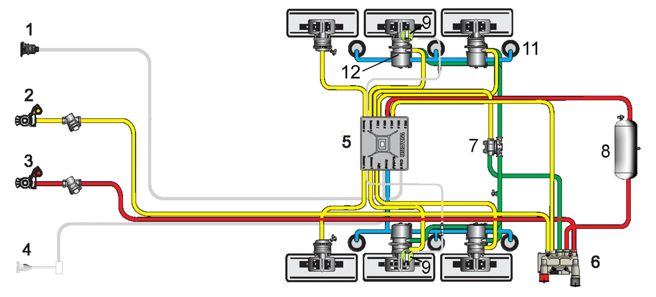
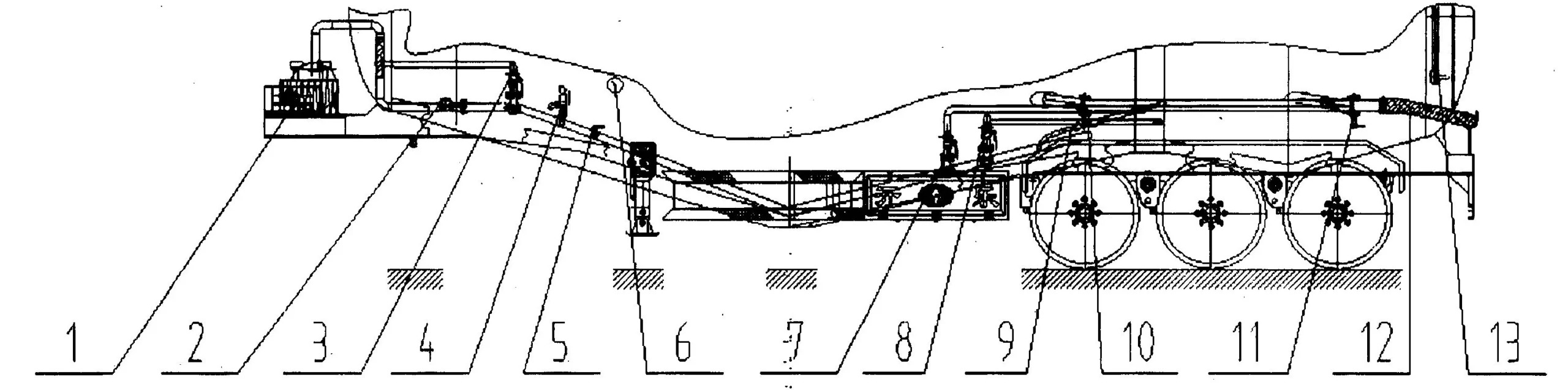
    Schematic diagram of a semi-trailer 2S/2M Anti-lock Braking System showing two wheel speed sensors and two pressure modulators configuration
    Fig 2: Typical Semi-Trailer 2S/2M ABS System Schematic
    1. ISO 7638 Power Supply 2. Service Line 3. Supply Line 4. Stop Light Power (ISO 1185, Optional) 5. TEBS Modulator (with pressure sensors) 6. Park Release Emergency Valve (PREV) 7. Overflow Valve 8. Service Brake Reservoir 9. ABS Speed Sensor 11. Suspension Air Bag 12. Spring Brake Chamber
    ⚠️ Expert Tip: Trailer ABS is designed to prevent loss of directional control, not necessarily to shorten braking distance. For long-wheelbase, high-center-of-gravity trailers, it is the absolute minimum safety requirement.

    2. RSS — The Rollover Prevention Guardian

    Roll Stability Support (RSS) is the most critical active safety system for trailers carrying high-risk loads. Different manufacturers use different names, but the core objective is identical — preventing trailer rollover by detecting lateral forces and automatically applying targeted braking:

    • RSS (Roll Stability Support) — ZF / WABCO
    • RSP (Roll Stability Program) — Knorr-Bremse
    • RSC (Roll Stability Control) — Haldex

    Why Do Trailers Roll Over?

    According to the ECE R111 standard, rollover becomes a critical risk when lateral acceleration reaches approximately 0.4G. For trailers carrying liquids, hanging meat, or unevenly distributed loads, this threshold is significantly lower due to dynamic load shifting.
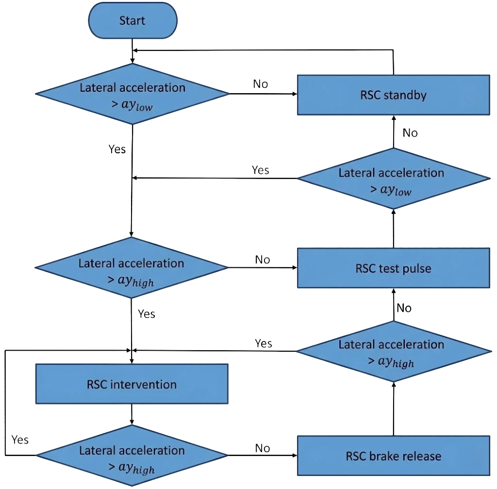
    Kales Trailer Roll Stability Control Logic Diagram showing the intervention flow from lateral force detection to automated brake application
    Fig 3: RSS Logic — The system actively applies brakes to specific wheels to counteract rollover forces.

    How RSS Reacts Faster Than a Human Driver

    RSS relies on physics sensors and algorithms — not driver reaction time. Here are the two mainstream working approaches:

    🔵 WABCO RSS — 3-Stage Intervention

    • Stage 1 (Warning @ ~0.2G): Light braking (~2 bar). Tests wheel grip and pre-charges the system — not intended to decelerate.
    • Stage 2 (Intervention @ ~0.3G): If lateral force increases, the system brakes hard to forcibly reduce speed.
    • Stage 3 (Correction): Higher brake pressure on inner-curve wheels prevents abrupt straightening, guiding the trailer through the turn.

    🟠 Knorr RSP — Smart Pulse Logic

    Test Pulse: When rollover risk is detected, the system sends a micro brake signal to check if the inner wheels decelerate.

    If wheels respond → they have grip. If they do NOT slow down → the wheels are lifting off the ground, confirming high risk. The system immediately applies full emergency braking.

    Critical Warning for Fleet Operators

    🚨 RSS Activation = Near Miss Event

    If the driver feels the trailer “tugging” back, or telematics reports an RSS activation, take it seriously:

    • Without this system, the vehicle would likely have rolled over.
    • It signals dangerous driving behavior (excessive cornering speed) or improper load distribution (center of gravity too high).
    • Mandatory Check: Frequent activation increases component wear. Always inspect brake linings and suspension systems after events. For mountain routes, also review our guide to brake fade on long downhill routes.

    !– ===== SECTION 3: EBS ===== –>

    3. EBS — Making Braking Fast, Precise, and Smart

    EBS (Electronic Braking System), also known as Brake-by-Wire, is not a single function — it is a comprehensive electronic control platform. EBS integrates sensors, actuators, and digital communication, often linking deeply with the trailer’s air suspension system to create a unified chassis management solution.

    When EBS is specified together with air suspension and matched heavy-duty trailer axles, the trailer can achieve more stable braking, better axle load control, and lower tire wear on export routes.
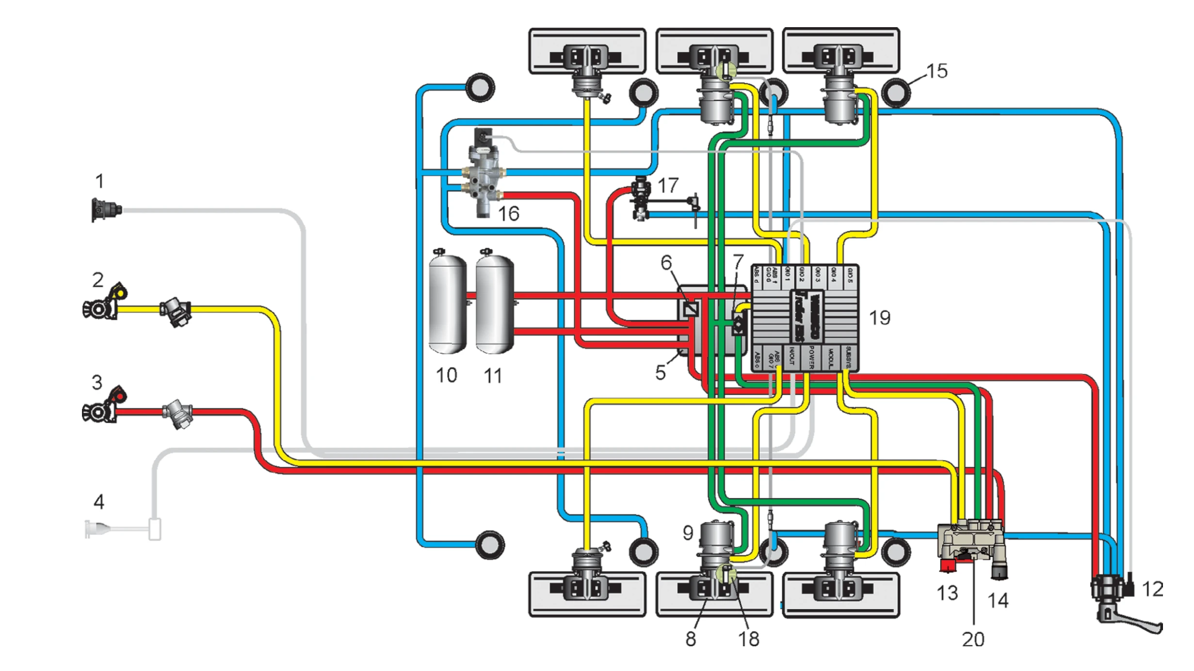
    Schematic diagram of a semi-trailer Electronic Braking System (EBS) integrated with air suspension control, showing modulator positions, sensor locations, and pneumatic circuit layout
    Fig 4: EBS System Schematic Integrated with Air Suspension
    1. ISO 7638 Power 2. Service Line 3. Supply Line 4. Stop Light (Opt.) 5. PEM 6. Overflow Valve 7. Charging Valve 8. Service Brake 9. Spring Brake Chamber 10. Service Reservoir 11. Air Suspension Reservoir 12. Raise/Lower Valve 13–14. Park/Release Buttons 15. Air Bag 16. Lift Axle Valve 17. Levelling Valve 18. ABS Sensor 19. TEBS Modulator 20. PREV

    From Pneumatic Delay to Digital Precision

    Traditional air brakes rely on the foot pedal to physically control air flow through long pneumatic lines — introducing significant delay. EBS replaces this with a pedal position sensor that reads the driver’s braking intent digitally. The ECU calculates required brake pressure for each axle based on speed, load, and wheel speed, then transmits commands via CAN Bus to Electro-Pneumatic Modulators (EPM) located near each wheel.

    Hidden Benefits: Why EBS Is More Than Fast Braking

    Modern EBS platforms (including systems configured by Kales Vehicle) use modular designs integrating the ECU, sensors, and pneumatic control into compact components that simplify chassis layout.

    🔍 The “Invisible Bonuses” of EBS

    • Coupling Force Control (CFC): Optimizes braking timing between tractor and trailer, preventing dangerous “trailer push” or “tugging” sensations.
    • Brake Blending: Intelligently distributes deceleration between endurance braking (retarders) and service braking (pads), extending component life.
    • Lining Wear Control: Automatically adjusts force distribution across axles to ensure even brake pad wear, reducing fleet maintenance costs.
    • Multi-Function Integration: Modern EBS modules integrate Lift Axle Control (LAC), RSS, TPMS, and overflow valves — eliminating complex external plumbing.

    ABS vs EBS: Head-to-Head Comparison

    Feature Traditional ABS (Pneumatic) Smart EBS (Electronic)
    Signal Transmission Air Pipes (Slow) CAN Bus Digital Signal (Near-Instant)
    Response Delay 0.3 – 0.6 Seconds ≈ 0 Seconds
    Core Functionality Anti-lock Only Anti-lock + Wear Balance + Coupling Control + Lift Axle
    AEBS Compatibility Poor (pneumatic lag) Full (zero-delay response)
    Maintenance Insight None Real-time diagnostics & wear data via telematics

    4. AEBS Synergy — The Danger of “Lag”

    AEBS (Advanced Emergency Braking System) decisions are made by the tractor’s radar and camera — but the trailer’s execution capability determines whether those decisions actually save lives.

    ❌ Trailer with ABS Only

    When the tractor triggers AEBS emergency braking, the ABS-only trailer reacts with a 0.3–0.6 second pneumatic lag. The trailer’s massive inertia pushes the tractor forward — extending braking distance and creating a dangerous “Pushing Effect” that can cause jackknifing or loss of control.

    ✅ Trailer with EBS

    The trailer receives the braking signal via ISO 11992 / ISO 7638 interface instantly. It applies full braking force with zero delay, creating a “Stretching Effect” that keeps the entire vehicle combination straight and stable throughout the emergency stop.

    5. The Pyramid of Trailer Intelligent Braking

    Semi-trailer braking technology follows a clear hierarchy. Each level builds on the one below it:

    L3 · ADVANCED

    RSS + AEBS

    Active Rollover & Collision Prevention

    L2 · PLATFORM

    EBS

    Electronic Brain · CAN Bus · Integrated Control

    L1 · FOUNDATION

    ABS

    Anti-Lock · Legal Baseline · Mandatory Standard

    Fig 5: Hierarchy of Semi-Trailer Intelligent Braking Technology

    Export buyer note: specify braking by route risk, not by brochure level

    For African export fleets, port corridors, mining roads and long downhill routes create different braking risks. A flatbed on short paved routes may start with ABS, but tankers, container chassis, dump trailers, high-center cargo and mountain corridors should be evaluated for EBS plus RSS/RSP. The higher system cost is easier to justify when one rollover, jackknife or thermal-fade incident can stop a fleet for days.

    The practical purchasing question is not “ABS or EBS?” but “Can the tractor power and communicate with the trailer system every day?” A missing or damaged ISO 7638 cable, incompatible tractor ECU, poor air quality, wrong sensor gap, contaminated connectors or mixed axle specification can make an advanced system behave like a basic system.

    6. Advice for Fleet Managers and Buyers

    As a professional trailer manufacturer, Kales Vehicle recommends considering the following when specifying braking systems:

    ① Think Long Term: Choose EBS + RSS

    If your fleet operates liquid tank trailers, livestock carriers, or high-value cargo trailers, we strongly recommend EBS with RSS. While the initial cost is higher, preventing a single rollover or jackknife accident pays for the upgrade many times over — in vehicle damage, cargo loss, insurance claims, and human cost.

    ② Never Ignore the ISO 7638 Cable

    🔌 A Fatal Blind Spot for Drivers

    The trailer’s ABS/EBS must be powered and communicate via the ISO 7638 coiled cable — the thickest connector between tractor and trailer.

    If unplugged or damaged, even the most advanced EBS becomes “brain dead” — reverting to basic pneumatic braking with zero anti-lock, zero anti-rollover protection. Always check before every trip.

    ③ Verify Tractor-Trailer Compatibility

    When purchasing, confirm the spec sheet states “EBS Supported” and “RSS/RSP Functionality.” Even if your tractor is equipped with the latest AEBS system, an outdated trailer braking system will compromise the safety of the entire rig. Read our tractor-trailer matching guide →


    Brake Release Gate: ISO 7638, Warning Lamps and First-Trip Diagnostics

    A trailer braking specification is not complete when the purchase order says ABS, EBS or RSS. It is complete only after the tractor, trailer, cables, sensors and diagnostics prove they work as one system. Treat this as a release gate before the first loaded dispatch and after any brake, axle, suspension or wiring repair.

    The evidence supports a strict gate. UNECE Regulation No. 13 frames braking performance and compatibility, ISO 7638 defines the tractor-trailer electrical connector family, and CVSA Brake Safety Campaign Results continue to show how often brake defects remove commercial vehicles from service.

    • Power and communication: connect ISO 7638, inspect pins and cable strain relief, and confirm the ABS/EBS warning lamp proves out then clears.
    • Wheel-end signals: inspect sensor position, tone ring condition and cable routing near axles, air suspension arms and moving brake components.
    • Air and response: check reservoir pressure recovery, audible leaks, modulator response and a low-speed progressive brake test before loading.
    • Diagnostics: save or clear fault codes with the correct tool, then record tractor ID, trailer ID, route risk and corrective action in the maintenance file.

    For fleet practice, connect this release gate with the semi-trailer troubleshooting guide and the Kales maintenance manual. A warning lamp, missing ISO cable or slow trailer response is a repair item, not a driver preference.

    7. Frequently Asked Questions

    Q: What is the difference between ABS and EBS on a semi-trailer?
    ABS prevents wheel lock-up using pneumatic control with electronic monitoring. EBS replaces pneumatic signal transmission with digital CAN Bus signals, reducing response delay from 0.3–0.6 seconds to near zero. EBS also integrates coupling force control, brake blending, lining wear management, and lift axle control — making it a complete electronic braking platform.
    Q: Does my semi-trailer need RSS (Roll Stability Support)?
    RSS is strongly recommended for tank trailers, livestock carriers, and any trailer with high or shifting center of gravity. Per ECE R111, rollover risk becomes critical at ~0.4G lateral acceleration — easily reached during highway curves. For liquid cargo with sloshing dynamics, the threshold is even lower.
    Q: Can a trailer with only ABS work with a tractor equipped with AEBS?
    Yes, but with significantly reduced effectiveness. The ABS-only trailer responds with a 0.3–0.6 second pneumatic delay, causing a “pushing effect” that extends braking distance and risks jackknifing. An EBS-equipped trailer receives signals instantly and brakes with zero delay.
    Q: What happens if the ISO 7638 cable is disconnected?
    The trailer’s ABS and EBS systems lose both power and communication. The trailer reverts to basic pneumatic braking with no electronic safety features — no anti-lock, no roll stability, no coupling control. This is a critical safety hazard. Always check the connection before departure.
    Q: Is EBS worth the extra cost for fleet operations?
    Yes. EBS reduces brake response time to near zero, extends brake pad life through intelligent wear balancing, and supports coupling force control for smoother combined braking. Preventing a single serious accident typically saves more than the cost of equipping an entire fleet with EBS.

    Safety Is the Biggest ROI

    In the era of intelligent transport, the trailer is no longer a silent partner. Don’t just compare volume and price — ask: “Is the braking system smart enough?”

    Kales Vehicle provides the safest, most durable semi-trailer solutions for global clients.

    Get a Custom Braking System Quote →

    Or message us on WhatsApp

    Need help applying this guide?

    Share your trailer type, payload, routes, operating climate, and photos with Kales. Our team can review the key points from this guide and recommend a practical specification for your fleet.

    1. Send photos of your tractor, trailer, or current component layout
    2. Confirm payload, road conditions, gradients, climate, and duty cycle
    3. Receive a specification or maintenance recommendation within 24 business hours

    Email: jennylee@kalestruck.com  |  WhatsApp: +86 131 5638 8843  |  Request a quote
  • Bulk Powder Tanker Trailer Guide: Cement Bulker Operation and Maintenance

    Bulk Powder Tanker Trailer Guide: Cement Bulker Operation and Maintenance

    Published: November 2, 2025 | Last updated: May 30, 2026

    In the heavy transport industry, efficiency is king. Whether you call it a pneumatic dry bulk trailer, a cement bulker, or a “silobas,” choosing the right equipment and operating it correctly is crucial for profitability. As a leading manufacturer exporting to Africa, Latin America, and Central Asia, Kales Vehicle Co., Ltd. presents this comprehensive guide to mastering your bulk powder tanker semi trailer.


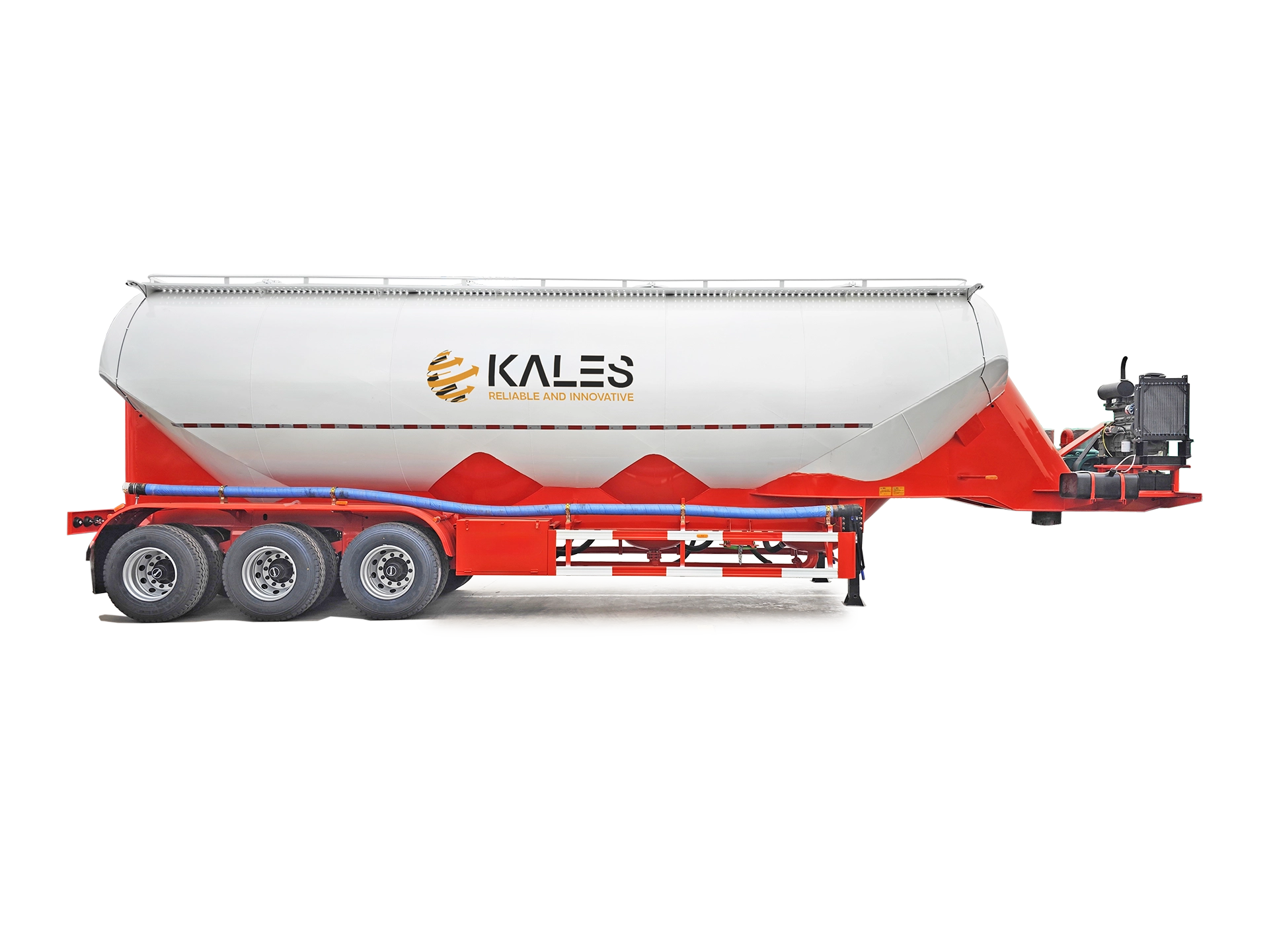
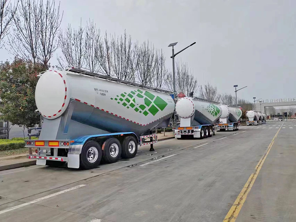
    4-Compartment 58m³ Powder Tanker trailer 58CBM Bulk Powder Transport trailer for sale
    Kales 3-axle bulk powder tanker semi trailer for cement transport ready for export.

    Technical basis and scope

    How this powder tanker guide is supported

    This guide is based on Kales dry bulk tanker specification practice, the operating data already shown in the article, and common pneumatic conveying principles used for cement, fly ash, lime powder and similar dry bulk materials. The key operating references are the Kales working-pressure range around 0.20 MPa, compressor speed range of 850-1000 RPM, fluidization canvas thickness of 6.5-8.0 mm, and typical unloading speed of 1.2-1.5 tons/minute when site conditions are suitable.

    The safety basis is wider than trailer specification. Public references such as HSE pressure systems guidance, OSHA compressed-air requirements, NIOSH Portland cement exposure data, and OSHA crystalline silica guidance support the same practical rule: control pressure, dust, moisture and stored energy before any hose is opened or any blockage is cleared.

    Use the numbers as ordering and maintenance references, not as permission to exceed the tank nameplate, relief-valve setting, compressor manual or local pressure-vessel rules. Before purchase, confirm cargo type, moisture sensitivity, unloading distance, silo height, local repair capability, tractor PTO compatibility, road condition, operator PPE and spare-parts availability.

    1. Why Choose Kales Pneumatic Dry Bulk Trailers?

    Designing trailers for rough terrain requires more than just steel; it requires engineering precision. Kales trailers are built to withstand the harsh road conditions of mining regions while delivering high-speed unloading.

    • ⚡ Fast Unloading Speed: Achieves 1.2–1.5 tons/minute, significantly reducing waiting time at the construction site.
    • 📉 Ultra-Low Residue: Our advanced fluidized bed design ensures a residue rate of <0.1%, saving you material costs on every trip.
    • 🛠️ World-Class Components: We use globally trusted brands for easy maintenance:
      • Diesel Engines: Reliable Weichai engines for consistent power.
      • Air Compressors: High-performance Bohai or Suzhou compressors (12m³ dual-cylinder).
      • Braking: Genuine WABCO braking systems for safety.
    • 🌍 Reinforced Chassis: Specially strengthened sub-frames and suspension systems designed for African and Central Asian road conditions.

    2. Selecting the Right Bulk Tanker Configuration

    Choosing between a V-shape, Cone-shape, or Tipper depends entirely on your cargo.

    🚛 Type A: Horizontal “V-Shape” Cement Trailer

    Best for: Cement, Fly Ash, Lime Powder.

    • Pros: Low center of gravity provides superior stability on highways. Simple internal structure allows for large capacity (up to 85m³).
    • Cons: Not suitable for coarse materials that don’t fluidize well.

    🚀 Type B: Vertical “Cone” Tanker

    Best for: Granules, Fertilizer, Coarse materials.

    • Pros: Gravity-assisted discharge ensures clean unloading of heavier particles.
    • Cons: Higher center of gravity requires careful driving on curves.

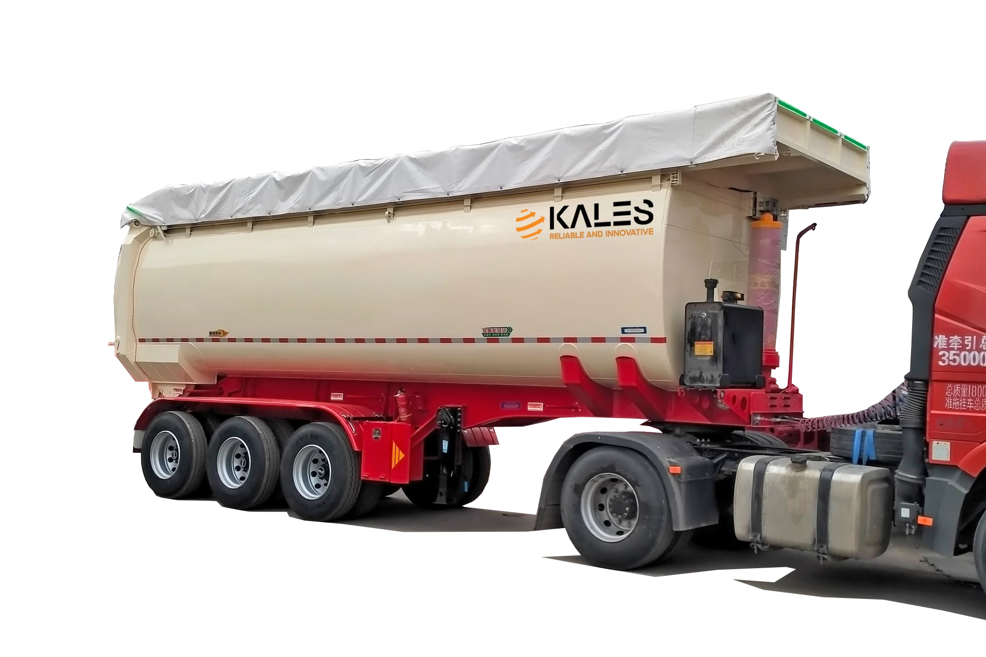
    4-Compartment 58m³ Powder Tanker trailer 58CBM Bulk Powder Transport trailer for sale

    🆙 Type C: Tipper (Lift-Type) Powder Tanker

    Best for: Food-grade Flour, PTA, Pharmaceutical Powders.

    • Pros: Zero residue makes it ideal for hygiene-sensitive cargo. Easy to clean internally.
    • Cons: Requires a flat, stable site for lifting to prevent tipping over.


    Buyer selection matrix: match tank design to cargo behavior

    The right dry bulk trailer is chosen by how the material flows, not only by cubic capacity. Cement and fly ash usually need a low-residue fluidized bed; fertilizer or granules may need cone discharge; food-grade or chemical powder may need lift-type cleaning access.

    • Cement and fly ash: choose a V-shape cement bulker when highway stability, high volume and controlled pneumatic discharge matter most.
    • Fertilizer, pellets and coarse powder: consider a cone tanker when gravity-assisted discharge is more important than the lowest possible center of gravity.
    • Food-grade flour, PTA or hygiene-sensitive powder: use a lift-type tanker only when the unloading site is flat, stable and trained for tipping operation.

    3. Power Source: Diesel Engine vs. PTO

    When ordering your Kales cement trailer, you must decide how to power the air compressor.

    Feature Independent Diesel Engine PTO (Power Take-Off)
    Flexibility High. Works with ANY truck head. Ideal for logistics companies with mixed fleets. Low. Must be paired with a specific truck head equipped with a PTO gearbox.
    Weight Heavier (Adds approx. 500kg). Lighter (Saves fuel during empty return trips).
    Maintenance Requires separate engine oil/filter changes. Low maintenance (uses truck engine power).


    Pneumatic Conveying System Schematic

    1. Air Compressor、2. Check Valve、3. Front Air Chamber Inlet Valve、4. Safety Valve (0–0.3 MPa)、5. External Air Source、6. Pressure Gauge、7. Middle Air Chamber Inlet Valve、8. Rear Air Chamber Inlet Valve、9. Secondary Blow Valve、10. Front Compartment Discharge Butterfly Valve、11. Rear Compartment Discharge Butterfly Valve、12. Discharge Hose

    4. Standard Operating Procedure (SOP) for Safe Unloading

    Follow this step-by-step guide to ensure safety and prevent damage to the fluidization canvas.

    ⚠️ Critical Safety Rules

    MOISTURE WARNING: Never allow water into the tank or air lines. Wet cement creates concrete blockages that can ruin the tank.
    PRESSURE HAZARD: Never open the manhole cover while the pressure gauge reads above 0 MPa.

    Step 1: Start-Up

    1. Connect the discharge hose to the silo inlet securely.
    2. Close the Pressure Relief Valve and Discharge Butterfly Valve. Open the Air Inlet Valves.
    3. Start the Weichai diesel engine.
    4. Adjust the hand throttle to the rated RPM. (Target: Keep Air Compressor at 850–1000 RPM. Do not over-rev!)
    5. Wait until tank pressure builds to 0.2 MPa.

    Step 2: Unloading

    1. Open the Secondary Blow Valve (Assist Valve) to clear the discharge pipe.
    2. Slowly open the main Discharge Butterfly Valve.
    3. Monitor the pressure. If it drops rapidly, the tank is emptying.

    Step 3: Cleaning & Shutdown

    1. When pressure drops to 0.15–0.10 MPa, alternate opening and closing the front/rear inlet valves. This “sweeping” action clears residue.
    2. Stop the engine. Open the pressure relief valve to release all remaining air before disconnecting hoses.

    5. Troubleshooting: How to Unblock a Cement Tanker Pipe

    A clogged discharge hose is a nightmare for drivers. If your pressure gauge spikes (>0.25 MPa) and discharge stops, follow this emergency procedure.

    The “Pulse” Technique (Emergency Unblocking)

    1. STOP: Do not increase the throttle; this will pack the powder tighter.
    2. CLOSE: Close the main Discharge Butterfly Valve.
    3. BLAST: Open the Secondary Blow Valve fully to blast air through the hose.
    4. PULSE: Quickly open and close the Discharge Butterfly Valve. The sudden pressure bursts often dislodge the blockage.
    5. MANUAL: If this fails, stop the engine, release ALL pressure, and physically check the rubber hose. A hard section indicates the clog.

    6. Fluidization Bed System Technical Explanation

    The core of a dry bulk tanker is its fluidization bed, which converts solid, static powder into a dynamic, liquid-like state. Without fluidization, dry cement behaves like dense sand, bridging over the outlet and locking inside the hopper. Understanding the mechanical components of this system is essential for troubleshooting discharge speed drop-offs.

    6.1. Fluidized Bed Architecture

    The interior floor of the V-shape tanker is sloped at a 40-degree angle, converging toward a central discharge trough. The trough is covered by a multi-layer fluidization fabric (commonly referred to as the fluidization canvas or slide belt). Below this canvas is the air chamber plenum box.
    The air compressor pumps dry air at 0.2 MPa (2.0 Bar) into this lower plenum. The air forces its way upward through the woven canvas, creating thousands of micro-jets. These air jets penetrate the cement powder, spacing the cement particles apart and reducing their friction coefficient to zero, allowing the fluidized cement to flow down the slope like water.

    6.2. Canvas Material and Weave Specifications

    Kales utilizes premium polyester-cotton composite slide belts (thickness: 6.5mm to 8.0mm). The fabric must possess exact air permeability specs (typically 2.0 to 3.5 m³/m²·min at 1.0 kPa pressure drop).
    If the canvas weave is too loose, the air passes through in big bubbles without fluidizing the cement, and powder can sift backward into the air chamber when the tank depressurizes. If the weave is too tight, it restricts airflow, resulting in slow unloading and increased compressor heat.


    7. Tank Operating Pressure Safety & Over-Pressurization Hazards

    A pneumatic dry bulk tanker is a certified Class II pressure vessel. Operating a pressurized vessel carries high safety risks, requiring mechanical safety relief valves and pressure gauges to prevent catastrophic tank ruptures.

    7.1. Pressure Limits and Relief Valve Calibration

    • Standard Working Pressure: 0.20 MPa (2.0 Bar / 29 PSI)
    • Max Operating Pressure: 0.22 MPa (2.2 Bar / 32 PSI)
    • Hydrostatic Test Pressure: 0.30 MPa (3.0 Bar / 44 PSI)
    • Safety Relief Valve Crack Pressure: Calibrated to open at 0.23 MPa to 0.25 MPa.
    ⚠️ Safety Warning: Relief Valve Maintenance
    Cement dust inevitably migrates into the safety relief valve spring mechanism. Over time, this dust reacts with moisture, forming concrete that locks the safety valve shut. Operators must manual-test the safety pull-ring weekly to ensure the spring moves freely. A locked safety valve can cause a catastrophic over-pressure explosion if the compressor limit is exceeded.

    8. Moisture Prevention & Air Dryer Maintenance

    Moisture is the absolute enemy of pneumatic bulk transport. When high-pressure air is compressed, its relative humidity spikes, leading to condensation. If water droplets enter the tank, they react with cement or fly ash, forming hard lumps of concrete that block the canvas pores, requiring manual chiseling to clean.

    8.1. Pre-Loading and Loading Protocols

    • Daily Compressor Purge: Before starting the Weichai engine, open the water drain cock at the bottom of the air compressor reservoir tank to purge condensed water.
    • Silo Vent Inspections: Ensure the loading hatch seals are clean and the rubber gasket is intact. Worn gaskets allow rainwater to enter the tank during transit.
    • Silo Air Supply: Ensure the silo’s receiving pipe is dry. If loading hot cement (above 80°C) during humid weather, condensation will form on the cool steel tank walls. In this case, the tank should be discharged immediately after arrival.

    9. Blower (Compressor) Calibration and Maintenance

    The air compressor is the engine of the unloading process. Kales tankers use high-performance Bohai or Suzhou 12m³ twin-cylinder reciprocating piston blowers or rotary screw compressors. Proper belt tension, speed calibration, and lubrication are vital to prevent premature wear.

    9.1. Speed and Belt Calibration

    The compressor must rotate within its target speed range of 850 RPM to 1000 RPM.

    • Under-speeding (<800 RPM): Insufficient airflow fails to fluidize the cement, causing pipe blockages and doubling discharge time.
    • Over-speeding (>1100 RPM): Generates excessive heat (discharge air temperature exceeding 140°C), which will melt the polyurethane lining of the discharge valves and scorch the fluidization canvas.
    • V-Belt Tension: Measure belt deflection. Pressing the belt midway between pulleys should yield 15mm to 20mm of deflection. Loose belts slip, reducing compressor speed and overheating the pulleys.

    9.2. Lubrication and Air Filter Maintenance

    • Oil Changes: Replace compressor gear oil after the first 50 operating hours, and every 500 hours or 6 months thereafter. Use high-performance ISO VG 150 gear oil.
    • Air Filters: Clean the compressor intake air filters weekly. In dusty mining areas, filters clog rapidly, starving the compressor of air and causing the cylinders to overheat.

    Export fleet note: Africa, Latin America and mining routes

    For export fleets serving cement plants, port terminals, mines and remote construction sites, the main failure pattern is not usually the tank shell. It is moisture entering the air system, clogged fluidization fabric, loose suspension fasteners, worn discharge seals or a compressor running outside its correct RPM range.

    If the route includes unpaved roads, steep access roads or long waiting time before unloading, specify spare fluidization canvas, discharge hose, butterfly valve seals, air filters, pressure gauges, safety-relief valve parts and compressor belts with the trailer order. These low-cost parts reduce downtime when the nearest workshop is far from the job site.

    Pre-delivery checklist before first loading

    • Pressure system: verify gauge reading at zero, safety valve test movement, manhole gasket condition and all air-line clamps.
    • Compressor system: check oil level, belt deflection, air filter cleanliness and target 850-1000 RPM under load.
    • Fluidization system: confirm canvas is dry, undamaged and evenly fixed before loading cement or fly ash.
    • Road readiness: retighten U-bolts after early service, inspect tank-to-frame rubber pads and keep a record of discharge time for each site.

    10. Maintenance Guide for Rough Roads

    ✅ Chassis & Suspension

    • U-Bolts: Retighten leaf spring U-bolts every 5,000 km. Loose bolts are the #1 cause of suspension failure on dirt roads.
    • Cushion Pads: Inspect the rubber pads between the tank body and chassis. Worn pads lead to metal-on-metal stress cracks.

    ✅ Fluidization System

    • Canvas Life: The breathable belt inside the tank usually lasts 1–2 years. If unloading slows down, replace it.
    • Water Separator: Drain the air compressor tank daily. Moisture is the enemy of the fluidization belt.

    Receiving-Silo Release: Dust, Pressure and Hose Disconnect Control

    Pneumatic unloading is a two-sided operation: the tanker must be ready, and the receiving silo must be able to accept air, powder and displaced dust. Many slow-discharge complaints are not caused by the trailer alone. A blocked silo filter, full bin, closed receiving valve or wet product in the line can raise pressure and push cement dust back toward the operator.

    Use a release check that combines pressure-system discipline and dust exposure control. HSE pressure systems guidance supports inspection of pressurized equipment, OSHA compressed-air requirements are relevant to safe air use, and NIOSH Portland cement data plus OSHA crystalline silica guidance explain why dust exposure should be controlled rather than treated as normal site mess.

    • Before unloading: confirm silo capacity, open receiving valve, working dust collector, secure hose clamps and a clean path around the discharge zone.
    • During unloading: track tank pressure, compressor RPM, hose vibration and dust collector behavior; stop if pressure rises without flow or dust escapes at the silo inlet.
    • Before disconnect: close the discharge valve, keep purge air only as specified, let the line drain, then depressurize the tank and hose to zero before loosening any clamp.
    • Before dispatch: record discharge time, pressure behavior, site name, product type and any moisture or blockage symptom for the maintenance log.

    For fleet control, pair this release record with the Kales semi-trailer maintenance manual and the semi-trailer troubleshooting guide. If discharge time grows at the same site, inspect the silo system before replacing tanker parts.

    Ready to Upgrade Your Fleet?

    Kales Vehicle Co., Ltd. delivers durable, high-performance transport solutions tailored to your market. Contact us today for technical diagrams and a custom quote.

    Get a Free Quote   View Product Catalog

    Need help applying this guide?

    Share your trailer type, payload, routes, operating climate, and photos with Kales. Our team can review the key points from this guide and recommend a practical specification for your fleet.

    1. Send photos of your tractor, trailer, or current component layout
    2. Confirm payload, road conditions, gradients, climate, and duty cycle
    3. Receive a specification or maintenance recommendation within 24 business hours

    Email: jennylee@kalestruck.com  |  WhatsApp: +86 131 5638 8843  |  Request a quote
  • Fuel Tanker Semi-Trailer Operation and Maintenance Manual

    Fuel Tanker Semi-Trailer Operation and Maintenance Manual

    Published: October 31, 2025 | Last updated: May 30, 2026

    Foreword: Designed for professional drivers and fleet managers, this manual provides the essential SOPs (Standard Operating Procedures) for the safe operation of Kales Fuel Tanker Trailers. Adherence to these guidelines ensures compliance with international HAZMAT transport regulations.


    Technical basis and safety scope

    How this fuel tanker manual is supported

    This manual is based on Kales export fuel tanker configuration, the API bottom-loading hardware described in the article, and dangerous-goods operating references already used in the text: API RP1004 for bottom-loading couplers, ADR/RID operating concepts, and DOT406 cargo tank concepts for tank integrity, vapor recovery, static grounding and compartment leak testing.

    For external safety context, the guide references OSHA 1910.106 for flammable liquids, PHMSA 49 CFR 178.345 cargo tank specifications, PHMSA 49 CFR 178.346 DOT 406 cargo tank requirements, PHMSA 49 CFR 180.407 cargo tank inspection and testing, and the U.S. CSB Barton Solvents static-spark investigation. These sources support the same field priorities: bonding and grounding, overfill prevention, vapor control, leak testing, compartment integrity and documented inspection.

    The figures in this guide are operating references for trained fleets: P/V vent working pressure around +6 to +8 kPa / -2 to -3 kPa, pneumatic interlock pressure around 0.35-0.5 MPa, grounding continuity below 10 Ohms, and pneumatic leak testing at 35 kPa. Always follow the vehicle documents, terminal rules and local hazardous-goods law for the exact unit.

    1. Core Systems Overview

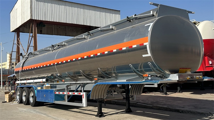
    1.1 🛢️ Tank Body & Construction

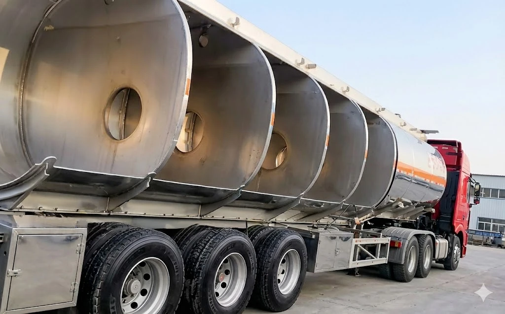
    • Material Standards: High-tensile Carbon Steel (Q345R), Stainless Steel, or Aluminum Alloy (5083). Compliant with ADR/RID and ISO standards for dangerous goods transport.
    • Compatible Media: Gasoline (Petrol), Diesel, Kerosene, and Jet Fuel.ℹ️ Note: For transporting edible oils or specific chemicals, ensure seals (gaskets) and lubricants are food-grade or chemically compatible. Never cross-contaminate without validation.
    • Anti-Surge Design: Equipped with internal Baffles (Thickness ≥4mm, flow area >20%) to minimize liquid surge and improve vehicle stability.
    • Capacity: 20,000L – 80,000L, available in Single or Multi-Compartment configurations.
    • Cross-sectional diagram of the bulkheads and baffles in the Kales fuel tank semi-trailer

    1.2 ⚙️ Manhole Assembly (Top Loading System)

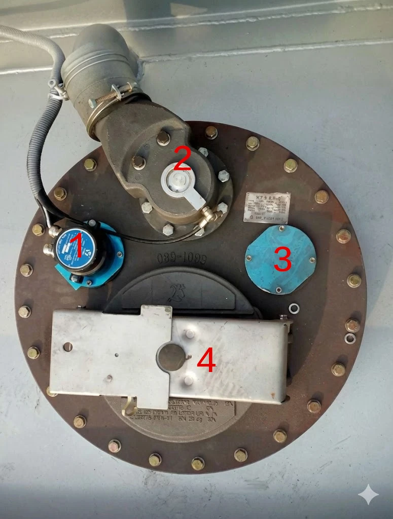
    Located on the tank top, the standard Euro-style Manhole (DN500) integrates:

    • Breather Valve (P/V Vent): Dual-mode Pressure/Vacuum relief.
      • Working Pressure: +6~+8 kPa (Pressure) / -2~-3 kPa (Vacuum).
      • Emergency Venting: 21~32 kPa.
    • Safety Interlock: The cover cannot be opened unless residual tank pressure is safe.
    • Overfill Prevention: Integrated with optic/thermistor sensors to trigger high-level alarms and shut off loading automatically.

    European-style manhole cover with integrated pressure

    European-style manhole cover with integrated pressure 1.Overfill prevention probe  2.Vapor recovery valve  3.Gauging hatch (or dip tube opening)  4.Manhole cover with integrated Breather Valve and Safety Interlock

    1.3 🔋 Bottom Loading System (API Standard)

    The core system for closed-loop, environmentally friendly loading operations. Fully compliant with API RP1004.

    • Emergency Foot Valve (Internal Valve): Pneumatically operated. Features a shear groove that snaps off during a collision, keeping the tank sealed to prevent spillage.
    • API Adapter Valve: The standard 4-inch valve with a 70° nose angle for dry-break coupling. Uses FKM (Viton) seals for fuel resistance.
    • Vapor Recovery Valve: Interlocked to open with the Foot Valve, returning volatile vapors to the terminal instead of venting to the atmosphere.
    • Pneumatic Control Block: Centralizes control for all valves, including the Master Air Valve.

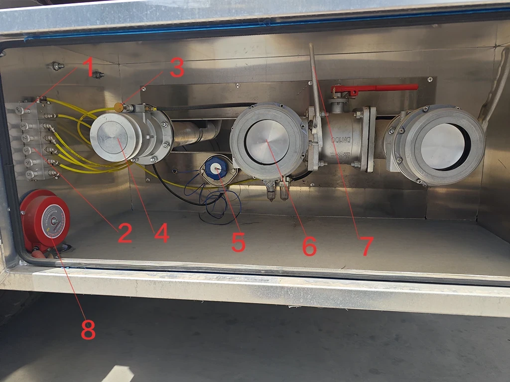
    Valve Box Components Legend:

    1. Master Air Valve: Activates the main pneumatic system.
    2. Compartment Switches: Pneumatic controls for individual Emergency Foot Valves.
    3. Vapor Recovery Switch: Opens the top vents (Interlocked with Master Valve).
    4. Vapor Recovery Valve: Outlet for recovering vapors during loading.
    5. Overfill Prevention Socket: Connection point for the terminal’s anti-overfill monitor.
    6. API Adapter Valve: Standard 4″ connection for bottom loading/unloading.
    7. API Valve Handle: Manually controls the valve opening and flow rate.
    8. Static Grounding Pin & Clamp: Essential connection point for static dissipation.

    2. Standard Operating Procedures (SOP)

    2.1 ⛽ Loading Procedure (Bottom Loading)

    A. Pre-Loading Checks

    1. 🛑 Park & Secure: Engine off, parking brake set, wheel chocks in place.
    2. ⚡ Static Grounding (CRITICAL): Connect the Bonding Cable to the terminal ground. Ensure the continuity light is green.*Wait 15 minutes after parking for static dissipation before connecting.
    3. 🔄 System Reset: Ensure all valves are closed and the air pressure gauge reads 0.35–0.5 MPa (50-70 psi).

    B. Loading Execution

    1. Connections:
      • Connect Overfill Probe Socket (Ensure no “Wet” alarm).
      • Connect Vapor Recovery Hose.
      • Connect Loading Arm to the API Adapter (Lock securely).
    2. Open Master Air Valve:
      • ✅ Action: Pull the “Master” switch.
      • 💡 Function: Engages the pneumatic system and forces the Vapor Vents open to balance tank pressure.
    3. Open Product Line:
      • Actuate the Foot Valve switch for the specific compartment.
      • Manually open the API Valve Handle.
    4. Start Loading: Follow terminal procedures. Monitor the Emergency Shut Down (ESD) button.
    5. Loading Sequence:
      • Recommended: Load evenly (e.g., Center first, or Front/Rear balanced).
      • ⚠️ PROHIBITED: Driving with a full load in only the front or rear compartment (prevents Kingpin/Suspension damage).

    C. Post-Loading Disconnection

    1. Close & Disconnect: Once the pump stops, close the Foot Valve first, then the API Valve. Disconnect hoses.
    2. Final Step: Disconnect the Grounding Cable last.

    2.2 💧 Unloading Procedure (Gravity Drop)

    🛑 DANGER: Vacuum Collapse Warning

    Liquid discharging creates a massive vacuum inside the tank.
    NEVER unload without opening the Master Air Valve (Vapor Vents).
    Failure to vent the tank will cause the tank body to implode (collapse) instantly.

    Execution Steps:

    1. Hose Connection: Connect Vapor Hose (if available) first, then the Discharge Hose.
    2. Equalize Pressure: Open the Master Air Valve.Check: Listen for the “hiss” or mechanical sound of the Vapor Vents opening on top.
    3. Discharge: Open the Foot Valve, then open the Manual Discharge Valve.
    4. Monitor: Never leave the vehicle unattended. Watch the sight glass.
    5. Drain & Finish: Tilt the hose to drain residue into the storage tank. Close valves in order: Foot Valve ➔ Manual Valve. Disconnect hoses.

    2.3 🚛 Special Operations

    🔩 Lift Axle Operation

    • Permitted: Only when the trailer is Unloaded (Empty).
    • Prohibited: NEVER lift the axle when carrying a load.

    ↩️ Self-Steering Axle (Reversing)

    • Procedure: Before reversing, drive forward 3–5 meters to straighten the wheels. Shift into Reverse and ensure the Locking Pin is engaged.
    • ⚠️ Warranty Void: Reversing without locking the steering axle will cause severe damage to the steering mechanism and tires. This is NOT covered under warranty.

    3. API Bottom-Loading Coupling Specifications

    Bottom loading via API couplers is the industry standard for safe fuel transfer. Standardizing these connections ensures that any terminal arm can mate securely without leaking. The Kales bottom-loading suite is manufactured in strict accordance with the API RP1004 specification.
    The API adapter’s profile must be measured periodically to prevent connection failures. Worn adapters will bypass the coupler latch locks, allowing the arm to disconnect under pressure, resulting in high-volume fuel spills.

    Parameter Spec API RP1004 Standard Limit Kales Factory Specification Field Tolerance & Verification Method
    Adapter Nose Diameter 101.6mm (4.000 inches) 101.55mm +/- 0.05mm Discard adapter if diameter measures <100.8mm (3.968″). Measure with caliper.
    Nose Angle / Bevel 70 degrees 70.0 degrees +/- 0.5° Verify profile using a go/no-go gauge. Inspect for nicks on locking lip.
    Max Flow Rating 2,400 L/min (635 GPM) 2,500 L/min Do not exceed loading pressure of 5.0 Bar (72 PSI) at the terminal arm.
    Poppet Leakage Threshold Zero visible leakage <0.05 ml per disconnect Replace Viton seal ring if leakage exceeds 3 drops per disconnect cycle.
    Interlock Air Pressure 0.35 – 0.70 MPa 0.50 MPa (5.0 Bar) Inspect pneumatic logic block pressure gauge. The system must lock out if pressure is <0.30 MPa.

    4. Closed-Loop Vapor Recovery System

    During loading or unloading, fuel vapors (which contain volatile organic compounds, VOCs) must not be vented to the environment. The closed-loop vapor recovery system routes these vapors back to the terminal or storage tank. If this system is restricted, the tank will experience either over-pressurization during loading or structural vacuum collapse during gravity unloading.

    4.1. System Components and Pipe Diameter

    The vapor recovery system starts at the top of each compartment, where a pneumatically controlled vapor vent valve is mounted on the manhole cover. These valves vent into a common 100mm (4-inch) aluminum pipe manifold running along the top of the tank.
    This pipe descends at the front of the trailer, terminating in a 4-inch API vapor adapter valve in the main discharge box. An integrated check valve prevents reverse flow from the terminal. A flame arrestor screen is installed inside the manifold to prevent external ignition sources from travelling into the tank compartments.

    4.2. Condensate Trap Maintenance

    As warm fuel vapors cool inside the vapor pipe manifold, they condense back into liquid fuel. This liquid settles at the lowest point of the vapor recovery pipe, near the bottom discharge valve.
    Required Maintenance: Operators must open the vapor recovery pipe drain valve weekly. If liquid fuel is allowed to accumulate, it will block the airflow, creating high backpressure that triggers the terminal’s emergency shut-off sensor during loading.


    5. Static Grounding & Bonding Verification

    Fuel flowing through pipes generates electrostatic charges. If these charges accumulate on the tank body, they can create a high-voltage spark when a hose or coupling is disconnected, igniting fuel vapors. Static grounding is the single most critical safety protocol during fuel transfer.

    5.1. Grounding vs. Bonding

    • Grounding: Connects the trailer chassis directly to the earth (ground rod) to bleed off accumulated static charge.
    • Bonding: Connects the tractor, trailer chassis, and loading terminal piping together electrically to ensure they are at the same electrical potential, preventing sparks when hoses are connected.

    5.2. Testing Grounding Continuity

    Do not assume the grounding strap is doing its job. Check the electrical resistance of the grounding circuit using this procedure:

    1. Locate the brass grounding pins on the trailer’s front nosebox and the copper grounding strap at the rear.
    2. Set your digital multimeter (DMM) to the Ohms (Ω) scale.
    3. Measure the resistance between the API adapter valve body and the copper grounding strap touching the ground.
    4. The resistance must measure less than 10 Ohms.

    Diagnosis: If the resistance is greater than 10 Ohms, check for paint or rust on the grounding bolt connections. Clean the mounting bolts down to bare metal and re-test. Replace the grounding copper braid if it is frayed or corroded.


    6. Tank Integrity & Compartment Leak Testing Protocol

    To comply with dangerous goods regulations (ADR / DOT406), the structural integrity of the tank shell and individual bulkheads must be tested annually. Leakage between compartments (bulkhead cracks) causes product cross-contamination (e.g., diesel mixing with premium gasoline), which is a severe safety and commercial risk.

    6.1. Pressure Decay Leak Test (Pneumatic Test)

    ⚠️ Safety Warning: Pneumatic Testing
    Never exceed the test pressure of 35 kPa (5.0 PSI / 0.35 Bar) during pneumatic testing. Applying high air pressure to a large tank creates massive stored energy. Over-pressurizing can cause the tank shell to rupture, risking fatal injuries. Use a pressure regulator and safety relief valve on the test air line.

    Procedure:

    1. Drain all compartments completely and flush them to ensure they are gas-free.
    2. Close all discharge valves, manhole covers, and vapor vents. Isolation plugs must be installed in place of the breather valves.
    3. Connect an air test manifold to the compartment’s vapor recovery port.
    4. Slowly pressurize the compartment to 35 kPa (5.0 PSI). Isolate the air supply.
    5. Monitor the pressure gauge for a period of 5 minutes.

    Pass/Fail Specs: The pressure drop must not exceed 1.0 kPa (0.15 PSI) over the 5-minute test duration. If the pressure drops faster, apply a soap-and-water solution to all weld seams, manhole gaskets, and valve flanges. The presence of bubbles will locate the leak path. Repeat this test for each compartment individually while adjacent compartments are at zero pressure to verify bulkhead integrity.


    Export operation note: fuel distribution routes and hot climates

    For export fleets working between terminals, depots, mines and filling stations, safety depends on routine discipline more than on one single component. Heat, dust, rough roads and mixed driver teams make small failures more likely: dry or cracked gaskets, loose U-bolts, blocked vapor lines, corroded grounding points and worn API adapter seals.

    When ordering a fuel tanker, include spare FKM/Viton seals, API adapter gaskets, grounding straps, P/V vent service parts, fire-extinguisher brackets, pneumatic fittings and valve box labels in the initial spare-parts package. These parts support safer field maintenance without improvising around fuel vapor and static electricity.

    Daily driver checklist before loading fuel

    • Static control: inspect grounding strap, grounding pin and terminal continuity light before any product connection.
    • Vapor control: confirm vapor vents open when the master air valve is activated and drain condensate from the vapor line as scheduled.
    • Valve control: check API adapter seal, emergency foot valve response, overfill socket condition and compartment switch labels.
    • Road safety: verify fire extinguisher tag, tire condition, U-bolts, suspension pads and that load is balanced by compartment.

    7. Maintenance & Safety Checklist

    7.1 🛠️ Preventive Maintenance Schedule

    Component Action Required Frequency
    U-Bolts Re-torque after the first 50-100km (Loaded) to compensate for rubber settling. Target torque is 300 Nm. New Trailer + Monthly
    Static Grounding Check the Earthing Strap for contact with the ground and conductivity. Measure resistance. 📅 Every Trip
    Valves Ensure all valves are fully closed. Do not leave in “Half-Open” position. 📅 Daily
    Pneumatics Clean air filters/strainers. Check system pressure. Drain condensate from separator. 📅 Weekly
    Breather Valves Professional inspection for sealing and pressure settings. Check spring tension. 📅 Quarterly
    Extinguisher Check pressure gauge (Green zone) and hose condition. Verify inspection tag. 📅 Monthly

    7.2 🚫 Critical Safety Rules

    1. No Overloading: Adhere strictly to the Gross Vehicle Weight (GVW) and compartment limits.
    2. No Ignition Sources: No smoking. Use only Non-Sparking Tools when working on the tank or valves.
    3. Confined Space Entry: NEVER enter the tank without: ① Full Depressurization ② Cleaning/Degassing ③ Forced Ventilation ④ Gas Testing ⑤ A Safety Spotter.
    4. Winter Precautions: If valves are frozen, DO NOT use open flames. Use steam or hot water to thaw.

    Transfer Control: Attendant, Emergency Stop and Disconnect Sequence

    Fuel tanker risk rises during loading and unloading because liquid movement, vapor displacement and hose connection all happen at the same time. Treat every transfer as a controlled operation, not a background task. One trained person should own the transfer from wheel chocking to final cap closure, and that person must be able to stop flow immediately.

    The control logic is supported by recognized safety references. OSHA 1910.106 addresses flammable-liquid handling, the PHMSA cargo tank inspection rule reinforces documented tank integrity, and the CSB Barton Solvents investigation shows why static bonding, grounding and equipment suitability cannot be treated as paperwork.

    • Before flow: chock wheels, set brakes, shut down unauthorized ignition sources, connect grounding/bonding, verify overfill protection and confirm the correct compartment/product match.
    • During flow: keep the attendant at the loading point, watch vapor line behavior, check API adapter leakage, monitor compartment level and stop if odor, alarm, pressure surge or abnormal hose movement appears.
    • Before disconnect: close flow first, allow line drain-down, close compartment valves, depressurize as specified by the terminal, then remove loading arm, vapor hose and ground connection in the approved sequence.
    • Before dispatch: confirm caps are locked, seals are installed, placards match the cargo, spill kit and extinguisher are present, and the driver has the terminal release record.

    For repeatable fleet control, pair this transfer record with the Kales semi-trailer maintenance manual and the semi-trailer troubleshooting guide. Electrical faults, brake defects and grounding failures should be solved before the tanker enters a fuel terminal.

    Need technical support or genuine tanker spare parts?

    Fuel tanker maintenance should not rely on improvised parts. Kales can help confirm API adapter parts, valve seals, grounding components, vapor recovery fittings and other export tanker spares for your exact configuration.

    ⚠️ Disclaimer
    This manual is based on the standard export configuration of Kales Vehicle Co., Ltd. Actual vehicle specifications may vary based on custom orders. Please refer to the technical documents delivered with your specific vehicle.
  • Tipper Trailer Operator Manual: Hydraulics, Safety and Maintenance

    Tipper Trailer Operator Manual: Hydraulics, Safety and Maintenance

    Published: October 31, 2025 | Last updated: May 30, 2026

    This comprehensive guide is designed for operators and fleet managers using Kales Tipper Semi Trailers. From understanding the advanced hydraulic tipping system to mastering safe unloading procedures and performing routine maintenance, this manual ensures maximum operational efficiency, safety, and longevity for your heavy-duty transport equipment.


    Technical basis and safety scope

    How this tipper trailer manual is supported

    This manual is based on Kales rear and side tipper operating practice, the hydraulic diagrams already shown in the article, and the pressure and stability limits stated in the guide. Key references include the hydraulic working range of 190-220 bar, relief-valve adjustment target of 190-200 bar under load, maximum lateral slope of 3 degrees, maximum wind speed of 30 km/h, and the requirement to dump only on firm, level ground.

    The safety basis is reinforced by public references on dump-body and workplace transport risk: NIOSH guidance on preventing injuries and deaths of dump truck operators, HSE guidance on workplace vehicle overturns, HSE quarry tipping-point guidance, HSE guidance on high-pressure hydraulic fluid injection, and an OSHA accident record involving a raised dump body. These sources support the same operating rule: assess the ground first, keep the tractor-trailer straight, stay clear of the raised body, and stop lifting if the load sticks or the body leans.

    Use this as an operator and maintenance guide, not as a replacement for the vehicle delivery documents. Before lifting any body, the driver must confirm PTO engagement, air pressure, cylinder condition, rear-door or side-gate locking, tractor-trailer alignment, ground bearing capacity and an exclusion zone around the trailer.

    1. Choosing the Right Kales Tipper: Rear vs. Side Tipping Trailer

    Selecting the correct unloading method is crucial for mining and construction logistics. Kales offers specialized tipping semi trailers designed for robust performance on rough terrain.

    ✅ The Kales Advantage: Whether utilizing a Rear Tipper or Side Tipper, all Kales trailers feature a unified, high-reliability hydraulic lifting mechanism. This ensures universal component compatibility, simplified maintenance, and proven performance across global operating conditions.

    1.1 Rear Tipper Trailer (End Dump)

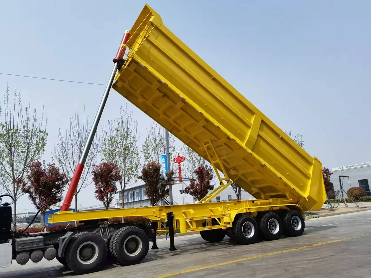
    • Mechanism: The cargo box tilts backward, discharging material from the rear tailgate using a powerful telescopic cylinder.
    • Best Applications: Mining transport, stone quarries, gravel yards, and heavy construction sites.
    • Kales Features: Built with a heavy-duty chassis, front-mounted lifting cylinder, and a reinforced balance frame for superior stability during off-road operations.
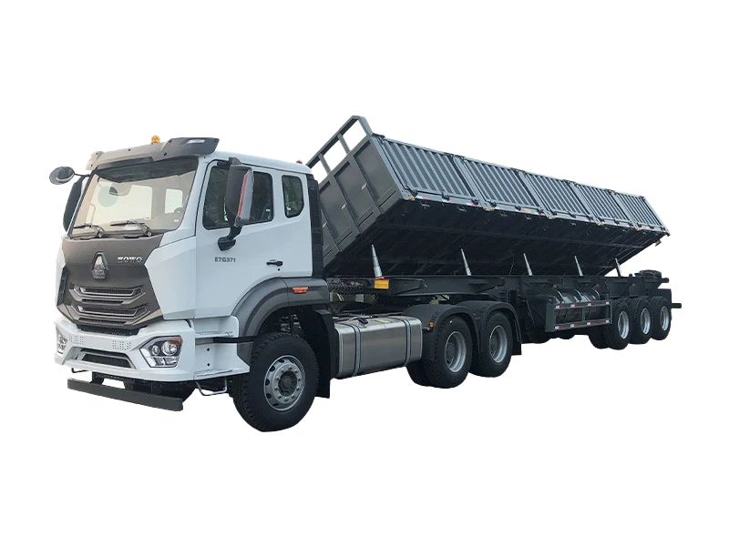
    Heavy duty rear tipper semi trailer with hydraulic cylinder extended for mining

    1.2 Side Tipper Trailer (Side Tipping Semi Trailer)

    • Mechanism: The body tilts to either the left or right side, ideal for efficient roadside discharge.
    • Best Applications: Narrow railway projects, road construction, and sites with height limitations where a rear dump trailer cannot operate.
    • Kales Features: Utilizes an advanced multi-cylinder synchronized tipping system. Precision hydraulic balancing ensures twist-free tilting even with uneven loads.
    Kales side tipper trailer unloading construction material on site

    Buyer selection note: rear tipper or side tipper?

    Rear tippers and side tippers solve different site problems. A rear dump trailer is usually preferred for sand, aggregate, coal and quarry work where there is enough straight space behind the vehicle. A side tipper is useful for windrow discharge, road construction and narrow unloading zones, but it needs stricter attention to side slope and gate locking.

    • Choose rear tipping when payload concentration, simple structure and deep dump piles matter most.
    • Choose side tipping when fast linear discharge along a road, berm or stockpile is more important.
    • Check maintenance capacity before ordering side tippers, because hinges, side cylinders and locking mechanisms add inspection points.

    2. The Core: Kales Hydraulic Tipping System Explained

    Kales tipper trailers rely on a mature high-pressure hydraulic system (~18-22 MPa / 180-220 Bar), known for rapid response and precise lifting control under heavy loads.

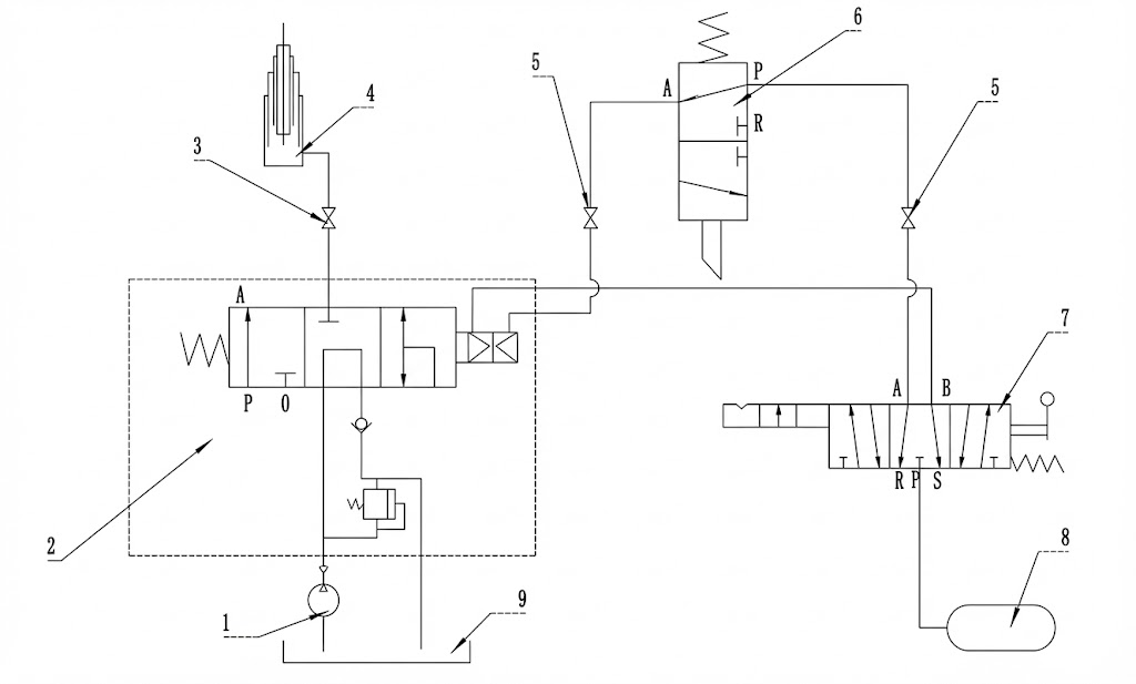
    Hydraulic System Diagram for Rear Tipper Trailer

    Rear Tipper Hydraulic Principle Diagram

    1. Gear Pump (Hydraulic Power)
    2. Pneumatic Control Valve
    3. PTO (Power Take-Off)
    4. Telescopic Lifting Cylinder
    5. Quick Coupling Fitting
    6. Limit Valve (Safety Stop)
    7. Manual Cab Control
    8. Air Source
    9. Hydraulic Oil Tank


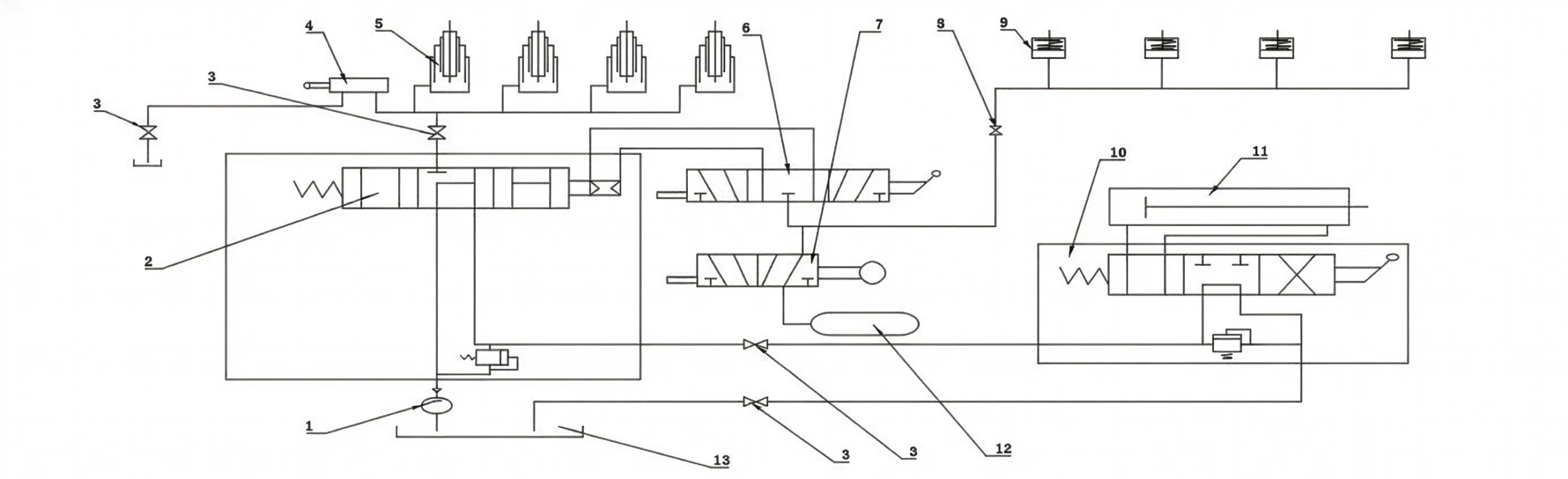
    Side Tipper Trailer Hydraulic Lifting System Diagram

    Side Tipper Hydraulic Principle Diagram

    1. Hydraulic Pump
    2. Directional Control Valve
    3. PTO Unit
    4. Hydraulic Limit Valve
    5. Side Shift Cylinders
    6. Tipping Control Valve
    7. Side Door Locking Cylinder
    8. Pneumatic Fitting

    Key Hydraulic Components

    • Power Unit (PTO Pump): Connects to the truck tractor gearbox to drive fluid flow.
    • Control Unit (Valve Block): The “brain” of the tipping system.
      • In-Cab Valve: Manual lever (Lift / Neutral / Lower).
      • Limit Valve: Automatically stops the tipper body at max angle to prevent cylinder over-extension.
    • Actuator (Hydraulic Cylinders): Hardened, chrome-plated cylinders designed for heavy-duty cycles and harsh environments.

    3. Step-by-Step Operating Guide

    ⚠️ Critical Safety Checklist:

    • Park on solid, level ground (Slope ≤3°). Never dump on soft soil or uneven terrain.
    • Engage the tractor parking brake completely.
    • Ensure no overhead obstructions (power lines, bridges) typically found in construction zones.

    3.1 Preparation (Side Tippers Only)

    1. Unlock the side gate using the pneumatic switch.
    2. Manually release any mechanical safety hooks on the cargo body.
    3. Check hinge pins: Ensure pins are locked on the correct side for discharge.

    3.2 Lifting the Trailer Body

    1. Depress clutch pedal and engage PTO switch. Slowly release clutch.
    2. Move in-cab lever to “LIFT”.
    3. Gently increase engine RPM to control lift speed. Smooth operation prevents chassis stress.
    4. To pause: Disengage PTO and move lever to “Neutral”.

    3.3 Lowering the Trailer Body

    1. Disengage PTO.
    2. Move control lever to “LOWER”.
    3. Gravity will lower the tipper box. Control descent speed by feathering the lever.

    4. Troubleshooting: Tipper Hydraulic Faults

    Use this guide to diagnose common issues with your tipping semi trailer.

    Symptom Most Likely Cause Quick Check Action
    Tipper Won’t Lift Electrical Issue (PTO) Check fuse; Listen for solenoid “click” when engaging PTO.
    Pneumatic Issue Check truck air pressure; Check for blocked air lines to the control valve.
    Hydraulic Issue Check if Limit Valve is stuck. Check hydraulic oil level.
    Tipper Won’t Lower Pneumatic Control Failure Check air lines on the lowering side of the valve. Check for stuck main spool.
    Slow Lifting Speed Pump Wear / Air Leaks Check engine RPM; Listen for air hissing; Check gear pump condition and relief pressure.
    Body Vibration/Jitters Low Hydraulic Oil / Aeration Stop immediately. Check oil tank sight glass to prevent pump cavitation. Bleed air from cylinders.
    🔧 Pro Tip: The most common cause for “No Lift” is a stuck Limit Valve due to mud or rust from off-road sites. Clean and lubricate regularly.

    5. Hydraulic Pressure Diagnostics & Relief Valve Calibration

    The hydraulic lifting mechanism of Kales rear and side tippers is a high-performance system operating at peak pressures between 190 Bar (19 MPa) and 220 Bar (22 MPa). Operating outside these safety limits can either render the trailer incapable of lifting its rated payload or lead to catastrophic component failure, such as ruptured steel hoses or damaged cylinder stages.

    5.1. Pressure Measurement Procedure

    To verify the operating pressure of the hydraulic system, follow this testing procedure:

    1. Locate the high-pressure test port on the side of the main pneumatic directional control valve (tipping valve).
    2. Connect a calibrated 0-400 Bar (0-40 MPa) fluid-filled pressure gauge to the test port using a high-pressure test hose.
    3. Fill the tipper trailer to its maximum rated capacity.
    4. Engage the PTO, place the cab lever in the “LIFT” position, and monitor the pressure gauge as the cylinder starts its primary telescopic stage.
    5. The pressure should rise rapidly, peaking as the cylinder lifts the heaviest initial load, and then stabilize.

    Diagnosis: If the pressure does not exceed 150 Bar and the cylinder fails to lift, the relief valve is set too low or the gear pump has internal wear, letting oil bypass the gears. If the pressure exceeds 240 Bar, shut off the PTO immediately. High pressure will damage the seal rings of the cylinder stages.

    5.2. Adjusting the System Relief Valve

    If adjustments are needed, locate the pressure relief adjustment screw on the tipping valve block:

    • Loosen the locking nut.
    • Using an Allen key, turn the adjustment screw clockwise to increase the relief pressure (typically 1 turn increases pressure by approx. 30 Bar).
    • Turn counter-clockwise to decrease the pressure setting.
    • Tighten the locking nut once the target pressure of 190-200 Bar under load is achieved.

    6. Safe Dumping Ground Assessment Guide

    A dump trailer is highly vulnerable to tipping over during the last stages of the lift. As the cylinder extends, the trailer’s center of gravity moves upward and backward. If the ground under the tires settles unevenly, even by a few inches, the trailer will lean, twisting the chassis and causing a rollover.

    6.1. Soil Bearing Capacity Assessment

    Before initiating any dump operation, the operator must assess the ground condition. Different soil types have varying load-bearing capacities under heavy wheel loads.

    Ground Surface Type Estimated Bearing Capacity Safety Risk Level Operator Action / Precautions
    Compacted Gravel / Asphalt High (>300 kPa) Low Risk Standard operation. Ensure tractor and trailer axles are in a straight line.
    Dry, Compacted Soil / Clay Medium (150-250 kPa) Moderate Risk Check for hidden underground voids. Re-check level after the first cylinder stage extends.
    Loose Sand / Mud / Wet Fill Low (<100 kPa) Critical Danger Do not dump. Tires will sink unevenly as weight transfers backward. Reposition to compacted ground.
    Freshly Backfilled Excavations Extremely Low Critical Danger Prohibited. The edge of the bank can collapse under the trailer’s rear dual wheels. Keep axles at least 3 meters away from slope edges.

    6.2. Environmental and Operation Limits

    • Maximum Lateral Slope: 3 degrees. If the trailer leans more than 3 degrees sideways, do not attempt to lift the body.
    • Maximum Wind Speed: 30 km/h (18 mph). High crosswinds acting on the large surface area of an extended tipper body create massive tipping forces.
    • Axle Alignment: The tractor and trailer must be aligned in a straight line. Jackknifed dump units are significantly more prone to rollover because the tractor cannot stabilize the trailer sideways.

    7. Telescopic Cylinder (Hyva / Kales OEM) Maintenance & Seals

    The front-mounted telescopic cylinder is the most valuable and highly stressed component of the tipper. Kales utilizes premium multi-stage cylinders (typically 4 or 5 stages depending on body length) with hard-chrome plating on all sliding sleeves.

    7.1. Cylinder Greasing and Inspection

    The cylinder pivots on two main points: the lower chassis trunnion mount and the upper body cross-head pin. These points experience massive loads during the initial lift stage.

    • Lower Trunnion Pins: Grease every 50 operating cycles using a lithium grease with solid molybdenum disulfide (MoS2) additives.
    • Upper Cross-head Bearing: Grease every 50 cycles. Inspect the retaining clips for wear or bending.
    • Sleeve Inspection: Wipe down extended sleeves weekly with a clean cloth to prevent dust and grit from damaging the wiper seals. Inspect for scratches, pitting, or chrome peeling.

    7.2. Troubleshooting Cylinder Seal Leaks

    If hydraulic oil film is visible on the cylinder sleeves when extended, it indicates a failing stage seal. Follow this diagnostic matrix:

    • Light Oil Film: Normal. A microscopically thin film of oil is required to lubricate the internal polyurethane seals.
    • Dripping Oil: Failing gland seal or damaged wear ring. Replace seal kit immediately. Running a leaking cylinder risks cylinder scoring and environmental contamination.
    • Stage Creep: If the tipper slowly lowers itself when the lever is in “Neutral”, the seal rings on the lower stages are bypassing oil internally, or the directional control valve spool is worn.

    Dump-site checklist before lifting the body

    • Ground: confirm compacted, level ground; stop if one wheel set sinks or the lateral slope exceeds 3 degrees.
    • Vehicle line: keep tractor and trailer straight. Do not lift when jackknifed or when rear wheels are close to a bank edge.
    • Hydraulics: check PTO, air control, relief-valve setting, hoses and cylinder stages before lifting under load.
    • Load: remove sticky material buildup and avoid lifting if cargo is frozen, bridged or stuck to one side of the body.

    Export fleet note: mining, quarry and rough-road operation

    For export fleets running in mines, quarries and remote construction sites, most tipper problems start as small inspection misses: loose U-bolts, dry cylinder pivots, contaminated hydraulic oil, bent door locks, worn suspension pads or operators dumping on soft shoulders.

    Order a spare-parts kit with hydraulic hoses, seal kits, PTO air fittings, hinge pins, grease nipples, rear-door or side-gate lock parts and hydraulic return filters. These parts are cheaper to stock than a trailer rollover, bent cylinder or blocked mine haul road.

    8. Maintenance Schedule & Lubricants

    8.1 Hydraulic Fluid Specifications

    Climate Condition Recommended Oil (ISO) Performance Benefit
    Winter (Cold Regions) L-HM 32 Anti-Wear Low viscosity ensures fast flow and prevents pump cavitation during cold starts (down to -20°C).
    Summer (Hot/Tropical) L-HM 46 Anti-Wear High viscosity protects the pump and directional valve spools in high-temperature environments (e.g., Africa/Middle East/SE Asia).

    8.2 Maintenance Checklist

    • Daily: Check for leaks in hoses and the hydraulic tank. Verify PTO engagement and check oil level on dipstick.
    • Weekly: Grease cylinder pins, lower trunnion mounts, and tailgate hinges with Heavy Duty Lithium Grease.
    • Monthly: Retorque structural bolts on the chassis frame and tipping hinge pins. Target torque is 350 Nm.
    • Every 6 Months: Drain hydraulic oil tank completely. Clean the suction strainer screen and replace the high-pressure return line filter. Refill with fresh hydraulic oil.

    Raised-Body Lockout: The Step That Prevents Fatal Tipper Accidents

    The highest-risk moment in tipper work is not normal driving; it is inspection, cleaning or repair while the body is raised. A telescopic cylinder is a lifting device, not a mechanical safety support. If a hose fails, a valve shifts, a PTO is engaged by mistake or sticky cargo suddenly releases, the body can drop or roll the vehicle without warning.

    This is why NIOSH dump truck safety guidance focuses on preventing injuries and deaths around dump bodies, and why quarry operators treat tipping points as controlled work zones under HSE tipping-point guidance. Hydraulic inspection also needs caution because high-pressure hydraulic fluid injection can cause serious injury even from a pinhole leak.

    • Before lifting: confirm ground bearing, tractor-trailer alignment, overhead clearance, wind condition and a no-person exclusion zone.
    • During lifting: keep PTO speed steady, watch for body lean, stop if cargo bridges, and never shake the body by abrupt clutch or valve operation.
    • Before inspection: lower the body whenever possible; if raised access is unavoidable, use the correct body prop or manufacturer-approved support before anyone enters the hazard area.
    • Before release: disengage PTO, return the control lever to neutral, confirm the body is fully seated, inspect hoses for fresh oil and record any repeated slow-lift or drift-down symptom.

    For fleet control, connect this raised-body release record with the Kales semi-trailer maintenance manual and the semi-trailer troubleshooting guide. That makes hydraulic faults visible before they become roadside failures.

    Final Thoughts: Safety is the Operator’s Responsibility

    Most Kales dump trailer accidents are preventable. By ensuring solid level ground, verifying operating pressure, and maintaining the telescopic cylinder, you protect your driver, your cargo, and your equipment.

    Need Professional Technical Support or Tipper Spare Parts?

    Don’t let a hydraulic failure disrupt your logistics operations. Our engineering team can supply genuine replacement valves, PTO pumps, and seal kits.

  • Semi-Trailer Troubleshooting: Brake, ABS, Tire and Electrical Faults

    Semi-Trailer Troubleshooting: Brake, ABS, Tire and Electrical Faults

    Published: October 30, 2025 | Last updated: May 30, 2026

    Keeping your Kales semi-trailer in top condition is essential for safety, compliance, and operational efficiency. Even high-quality trailers can develop issues over time due to wear, improper maintenance, or harsh operating conditions.

    This comprehensive guide outlines the most common Kales semi-trailer problems, their root causes, and step-by-step solutions—organized by system for quick reference. Whether you’re a fleet manager, owner-operator, or maintenance technician, this troubleshooting resource will help you minimize downtime and maximize trailer lifespan.

    Technical basis and diagnostic scope

    How this semi-trailer troubleshooting guide is supported

    This guide combines Kales service experience on export semi-trailers with public inspection logic used by professional fleets. The inspection framework follows the same safety priorities described in the CVSA North American Standard Inspection levels: brakes, air leakage, suspension, axles, wheels, tires, lighting and coupling hardware must be checked before a loaded vehicle returns to service.

    The brake and wheel-end sections are also supported by CVSA Brake Safety Day inspection results, which show why brake defects remain a fleet priority. Tire diagnosis references NHTSA tire safety guidance, and electrical diagnosis references the SAE J560 seven-conductor connector standard. For ABS, EBS and RSS system context, this article links back to the Kales semi-trailer braking systems guide.

    Exact service limits still come from the component fitted to the trailer: axle, brake chamber, slack adjuster, air valve, ABS ECU, suspension, landing gear and tire maker documents. If a trailer has air loss, smoking hubs, loose wheels, brake fire smell or unstable steering, park safely and call qualified service before moving again.

    Priority Typical symptom Action
    Stop now Hot hub, air loss, loose wheel, brake smoke Park, chock, isolate and repair before movement
    Repair before loading ABS fault, uneven tire wear, light failure Diagnose system and confirm correction
    Planned service Noise, slow landing gear, minor seepage Record, monitor and schedule parts
    ⚠️ Safety Warning: Always secure the trailer with wheel chocks and jack stands before performing under-chassis inspections. Ensure the air system is depressurized before disconnecting lines.

    1. Brake System Failures

    The brake system is critical for road safety. Ignoring early warning signs can lead to accidents or roadside violations.

    1.1. Weak or Delayed Braking

    Symptom Likely Cause Solution
    Reduced braking power Excessive clearance (drum/lining) Adjust clearance to manufacturer specs
    Worn brake linings Replace brake shoes
    Air leakage in brake circuit Inspect lines and valves; repair leaks
    Faulty emergency relay valve Replace repair kit or valve assembly

    1.2. Brakes Won’t Release (Dragging)

    Symptom Likely Cause Solution
    Brakes remain engaged Low air pressure (<0.8 MPa) Restore air pressure to 0.8 MPa
    Broken return spring Replace spring in brake chamber
    Bent pushrod Replace or straighten pushrod
    Incorrect stroke Re-adjust stroke length per Kales specs

    1.3. ABS Warning Light On (New)

    Symptom Likely Cause Solution
    Amber ABS light stays on Sensor gap too wide Push ABS sensor fully against tone ring
    Damaged sensor cable Inspect wiring for cuts; replace sensor
    🔧 Pro Tip: Always perform a full air system leak test during pre-trip inspections to catch issues early.

    2. Suspension System Issues

    Suspension problems affect ride quality, tire wear, and cargo stability.

    2.1. Noises from Suspension

    Symptom Likely Cause Solution
    Clunking or rattling Broken leaf spring Replace spring assembly
    Loose U-bolt nuts Tighten to specified torque (refer to manual)

    3. Fifth Wheel (Kingpin) Problems

    3.1. Handle Won’t Lock or Feels Loose

    Symptom Likely Cause Solution
    Handle doesn’t engage fully Improper position of locking hook Adjust set screw on right side:
    • Clockwise → reduces play (tighten)
    • Counter-clockwise → eases operation (loosen)

    4. Axle & Wheel Assembly Faults

    4.1. Wheel Wobble or Vibration

    Symptom Likely Cause Solution
    Visible oscillation Loose lug nuts Retorque to manufacturer specification
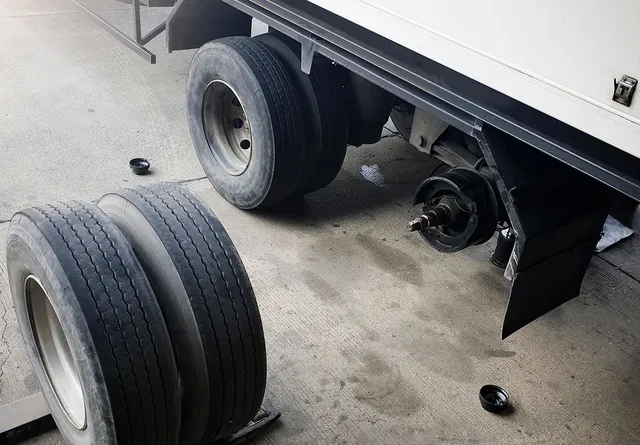
    Seized axle bearing Replace bearing immediately
    Bent rim Replace wheel assembly

    4.2. Overheated Wheels (Hot Hubs)

    Symptom Likely Cause Solution
    Hot hubs after trip Seized bearing / No grease Replace bearing; use correct Grease (ZG-4 / Lithium)
    Brake drag Diagnose brake system (See Section 1)
    Over-tightened axle nut Loosen and re-torque to spec

    4.3. Uneven Tire Wear

    Symptom Likely Cause Solution
    Shoulder wear / Feathering Axle misalignment Adjust tie rods; check alignment
    Center wear Over-inflation Inflate to Kales-recommended PSI
    Cupping Worn suspension parts Replace bushings or shocks

    5. Landing Gear Malfunctions

    5.1. Hard to Crank or Stuck

    Symptom Likely Cause Solution
    Excessive resistance Poor lubrication Apply grease to gears and screw
    Bent leg tubes Replace damaged leg section
    Grinding noise Worn gears Disassemble and replace gear set

    6. Electrical System Failures

    Electrical faults compromise visibility. Most issues are caused by poor grounds or corrosion.

    6.1. Lights Not Working

    Symptom Likely Cause Solution
    Lights flickering / Dim Bad Ground Connection Clean chassis ground point; check for rust
    One light out Burned-out bulb Replace bulb; check socket corrosion
    No lights working Loose 7-way plug Clean contacts; spread pins for better fit

    7. Advanced ABS/EBS Diagnostics & WABCO Fault Code Troubleshooting

    Modern semi-trailers rely heavily on electronic safety systems. Kales semi-trailers utilize premium WABCO Electronic Braking Systems (EBS) or Anti-lock Braking Systems (ABS). When a system failure occurs, the amber ABS lamp illuminates on the trailer’s nosebox or the tractor’s dashboard, indicating that the Electronic Control Unit (ECU) has detected a diagnostic trouble code (DTC).

    Diagnosing these electrical brake codes without a computer interface is possible using WABCO’s blink code functionality. By turning the ignition switch or diagnostic button ON and OFF in specific intervals, the ABS lamp will flash out numerical codes (blink codes). Understanding these codes allows mechanics to pinpoint failures instantly.

    Blink Code Component / Fault Description Root Cause Recommended Repair Procedure
    4 – 1 Wheel Speed Sensor (Sens-Axle 1 L) Air gap too large; sensor disconnected; tone ring damage. Measure AC voltage at sensor while spinning wheel (should be >0.2V AC). Adjust sensor bracket clearance to <1.0mm.
    4 – 2 Wheel Speed Sensor (Sens-Axle 1 R) Excessive hub play; dirty sensor face; cut wiring harness. Clean road grime/metal shavings from sensor face. Verify wheel bearing play and tighten spindle nut if loose.
    4 – 3 Wheel Speed Sensor (Sens-Axle 2 L) Corroded connectors; sensor out of position. Inspect ABS cable routing. Push sensor until it physically contacts the tone ring; it will self-adjust during first wheel rotation.
    4 – 4 Wheel Speed Sensor (Sens-Axle 2 R) Short to ground; broken copper conductor inside jacket. Conduct continuity test between pins 1 and 2 of the sensor connector. Target resistance should range between 900 to 2000 Ohms.
    7 – 1 ABS Modulator Valve (LHS) Solenoid short circuit; internal coil burnt; loose ground. Unplug modulator harness and check resistance across solenoids. Clean pins with contact cleaner; replace valve if coil is open circuit.
    7 – 2 ABS Modulator Valve (RHS) Moisture in valve housing; electrical short to frame. Verify air dryer cartridge performance. Drain water from air tanks; replace relay valve if corrosion has reached electrical solenoids.
    14 – 1 ECU Power Supply Voltage Low voltage (<9.5V DC); bad ground connection on Pin 1. Inspect 7-way tractor plug. Measure voltage under load at pin 7. Clean main ground bolt on the trailer frame.

    When replacing a WABCO modulator valve, always torque the mounting bolts to 22-28 Nm (16-20 ft-lbs) to avoid housing distortion. Additionally, ensure the exhaust port is clear of mud or road debris. Blocked exhaust ports prevent the brakes from releasing, causing immediate shoe glazing and dragging brakes.

    8. 7-Pin (SAE J560) Electrical Harness Voltage Drop Testing

    Electrical failures account for a substantial percentage of trailer downtime, especially dim lights or flickering ABS warnings. The standard commercial connection is the SAE J560 7-pin plug, which supplies both constant and switched power. Corrosion or high-resistance joints can lead to a severe voltage drop, causing the ABS controller to malfunction (requiring a minimum of 9.5 Volts) while tail lights work normally.

    ⚠️ Safety Warning: Never use a sharp probe to puncture wire insulation during testing. Puncturing the outer jacket allows moisture to enter, leading to copper oxidation (green rot) that destroys the harness over time. Always probe at connector backs or splice boxes.

    8.1. SAE J560 7-Pin Plug Wiring Standard

    • Pin 1 (White): Ground Return (Heavy gauge – must support total trailer current)
    • Pin 2 (Black): Clearance, side marker, and identification lamps
    • Pin 3 (Yellow): Left-turn signal and hazard warning lamps
    • Pin 4 (Red): Stop lamps and anti-lock brake device power
    • Pin 5 (Green): Right-turn signal and hazard warning lamps
    • Pin 6 (Brown): Tail, license plate, and clearance lamps
    • Pin 7 (Blue): Constant auxiliary power for trailer ABS unit

    8.2. Voltage Drop Test Procedure

    A simple resistance check using a multimeter can be misleading because a single copper strand will show continuity, but will fail to carry the required load. To perform an accurate voltage drop test under load, follow these steps:

    1. Connect the trailer to the tractor and switch ON all lights and hazard signals.
    2. Locate the main splice junction box (usually mounted on the interior front crossmember of the trailer).
    3. Set your digital multimeter (DMM) to DC Volts.
    4. Measure the voltage directly between the positive terminal (Pin 7 or Pin 4) and the ground pin inside the junction box.
    5. Compare this reading to the voltage measured at the tractor battery.

    Diagnosis: The voltage drop must not exceed 0.5V DC. If battery voltage is 12.8V and junction box voltage is 11.2V (a drop of 1.6V), there is excessive resistance in the circuit. Typically, this is located at the nosebox socket terminals, which expand over time and lose clamping force. Use a J560 terminal cleaning tool to remove oxidation and spread the male pins slightly to restore contact tension.

    9. Tire Wear Diagnostics and Mechanical Root Causes

    Semi-trailer tires are a massive operating cost. Uneven tire wear is rarely a tire defect; it is typically a symptom of a mechanical problem in the suspension, alignment, or wheel ends. Understanding how to interpret wear patterns allows fleet managers to address the underlying cause before a tire blowouts occurs.

    Wear Pattern Visual Description Primary Mechanical Root Cause Corrective Action & Maintenance Spec
    Cupping / Scalloping Undulating dips around the tire circumference. Failed shock absorber; loose wheel bearing; worn spring bushings. Replace shock absorbers (inspect for hydraulic oil leaks). Tighten axle spindle nut using 3-step torque method to ensure correct bearing endplay (0.001″ to 0.005″).
    Feathering Tread blocks worn smooth on one side and sharp on the other. Axle misalignment (toe-in or toe-out). Measure distance between kingpin and front axle hub ends using an alignment bar. Ensure variance is within +/- 1.6mm (1/16″). Adjust axle collar adjusters.
    Shoulder Wear (One Side) Smooth wear isolated to the inside or outside shoulder. Bent axle tube; overloaded trailer causing axle camber deflection. Check axle camber using an electronic level. Replace axle tube if bent permanently. Do not exceed rated gross axle weight rating (GAWR).
    Center Wear Tread in the center worn significantly deeper than shoulders. Consistent over-inflation. Adjust cold tire pressure to match the load-inflation tables provided by the tire manufacturer (typically 100-110 PSI for standard dual assemblies).
    Flat Spotting / Diagonal Wear Isolated flat patches across the tread width. Seized brake adjuster; out-of-round brake drum; aggressive brake lockup. Verify automatic slack adjuster function. Check drum runout using a dial indicator (maximum allowable runout is 0.25mm / 0.010″). Replace drums if warped.

    10. Regional Environmental Challenges & Fleet Case Studies

    Kales semi-trailers operate in diverse global environments, each presenting unique wear patterns and failure modes. Maintenance schedules must be tailored to these conditions to prevent premature failures.

    10.1. Mountain Routes in Latin America (Brake Heat and Retarder Discipline)

    On Andean routes in Peru, Chile, Colombia and Bolivia, long downhill gradients put continuous heat into trailer brakes. The safest response is not to cool hot brake drums with water at random, because sudden temperature change can shorten drum life and hide the root cause of overheating. Treat repeated hot-wheel reports as a system fault: tractor retarder strategy, descent speed, brake adjustment, lining condition, axle load and driver technique must be reviewed together.

    Operational recommendation: For mining and mountain fleets, specify brake capacity before purchase, train drivers to descend in the correct gear, and inspect drums, linings, hub seals and ABS sensor wiring after severe routes. Fleets comparing drum, disc, ABS, EBS and RSS options should also review the Kales braking guide linked below.

    10.2. The Sahel Desert and West Africa (Abrasive Dust Contamination)

    Trailers hauling agricultural and construction goods along West African corridors (Côte d’Ivoire, Mali, Burkina Faso) face extreme dust and heat. Sand particles bypass standard air seals, entering the brake slack adjusters and wheel hub assemblies, where they combine with grease to form an abrasive grinding paste.

    Field-service pattern: dusty corridors and unpaved job sites
    Trailers hauling construction goods, aggregates or agricultural cargo on dusty routes often show the same fault chain: abrasive dust mixes with grease, air tanks collect water and fine particles, landing gear screws become stiff, and wheel-end bearings run hotter than normal. This pattern is common on West African corridors, quarry roads and dry-season construction sites.

    • Increase wheel-end, landing gear and slack-adjuster lubrication frequency during dusty seasons.
    • Purge air reservoirs more often where humidity, dust and compressor oil carryover are present.
    • Use protective boots where the operating route exposes screw shafts and adjusters to mud or sand.
    • Record repeated hot hubs or hard cranking as route-related maintenance data, not isolated driver complaints.

    Roadside Triage: Stop, Repair Before Loading, or Log for Service

    A troubleshooting guide is only useful if the driver, dispatcher and workshop make the same release decision. Treat air loss, smoking hubs, loose wheels, cracked tire casings, locked brakes and missing brake lights as stop-now faults. Move the trailer only after it is parked safely, chocked and checked by qualified service personnel.

    The evidence base supports this conservative triage. CVSA’s Brake Safety Campaign Results reported that the 2026 unannounced Brake Safety Day placed 574 of 4,021 inspected commercial vehicles out of service for brake-related violations. For tire-related triage, NHTSA tire safety guidance emphasizes inflation, tread, damage and load as safety-critical checks before a vehicle continues operating.

    • Red: park and repair before movement when there is air pressure loss, a hot hub, a brake that will not release, a loose wheel, exposed tire cord or failed stop/turn lamps.
    • Amber: repair before the next loaded dispatch when the ABS lamp is on, one lamp circuit is intermittent, a hub runs warmer than its axle mate, or tire wear shows a mechanical pattern.
    • Green: log for planned service when the fault is minor, repeatable and does not affect braking, steering, wheel retention, lighting visibility or load support.

    For yard release control, link the fault log with the semi-trailer coupling and pre-trip checklist. That creates one record from driver symptom to workshop cause and final release.

    Final Thoughts: Prevention Is Better Than Repair

    Most Kales semi-trailer failures stem from neglected maintenance or incorrect servicing. By following a structured inspection schedule—and addressing minor issues early—you can avoid costly repairs, roadside breakdowns, and safety incidents.

    Need Professional Technical Support or Replacement Parts?

    Don’t let trailer downtime impact your fleet’s profitability. Our engineering team can analyze your operational parameters and recommend the ideal components.

    Need help applying this guide?

    Share your trailer type, payload, routes, operating climate, and photos with Kales. Our team can review the key points from this guide and recommend a practical specification for your fleet.

    1. Send photos of your tractor, trailer, or current component layout
    2. Confirm payload, road conditions, gradients, climate, and duty cycle
    3. Receive a specification or maintenance recommendation within 24 business hours

    Email: jennylee@kalestruck.com  |  WhatsApp: +86 131 5638 8843  |  Request a quote
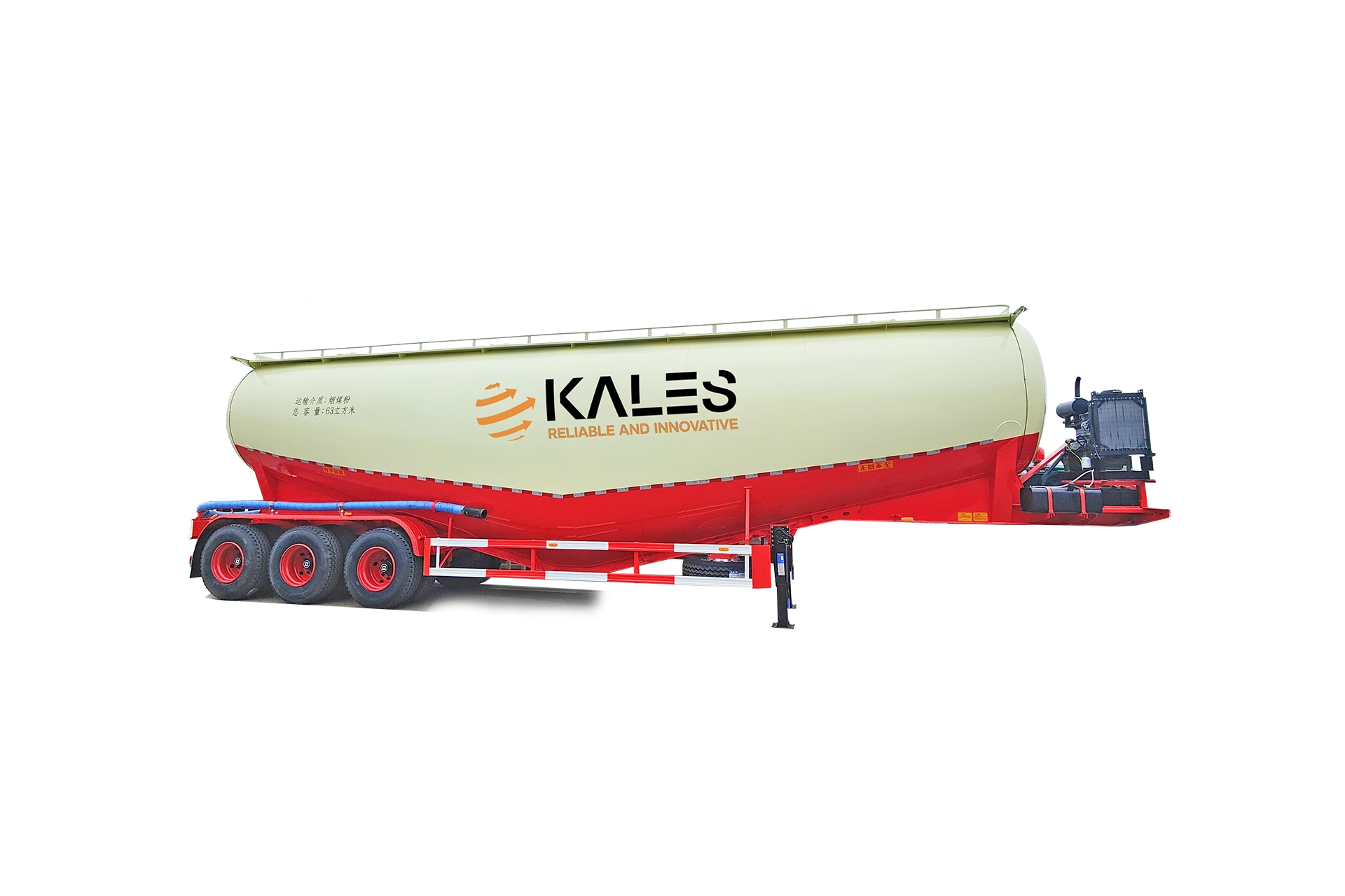
  • Semi-Trailer Lubrication Guide: Grease Points, Intervals and Field Checks

    Semi-Trailer Lubrication Guide: Grease Points, Intervals and Field Checks

    Published: October 30, 2025 | Last updated: May 30, 2026

    Proper lubrication is one of the most critical yet often overlooked aspects of Kales semi-trailer maintenance. Regularly greasing the right components with the correct lubricants not only ensures smooth operation but also prevents premature wear, enhances road safety, and significantly extends your trailer’s service life.

    In this guide, we’ll walk you through everything you need to know about lubricating your Kales semi-trailer—from recommended grease types and lubrication intervals to best practices that keep your fleet running efficiently.

    Technical basis and service scope

    How this trailer lubrication guide is supported

    This guide is based on Kales semi-trailer service practice and the grease grades already shown in the original maintenance table. The international reference point is the NLGI consistency grade: it describes grease stiffness, while the thickener type, base oil viscosity and EP additives decide whether the grease is suitable for wheel bearings, kingpin plates, landing gear or brake camshaft bushings.

    For evidence and terminology, the guide references ASTM D4950 automotive service grease classification, SKF bearing lubrication guidance, SKF lubricant selection information, the Timken lubrication selection guide, and Timken grease application data. These sources support the same workshop rule: temperature, load, water, dust and relubrication interval must be considered together.

    For fleets, do not choose grease by color or price alone. Use the trailer manual, component supplier instruction and operating route. A trailer on quarry dust, water crossings, port storage or mountain descents needs shorter service intervals than a highway trailer.

    Condition Lubrication response
    Dust, mud or water wash Shorten interval and purge contaminated grease where possible
    Hot hub or bearing noise Stop, inspect bearing and seal before adding grease
    Changing grease base Clean or purge old grease before switching thickener type

    Why Lubrication Matters for Your Kales Semi-Trailer

    Friction is the silent enemy of heavy-duty trailers. Without adequate lubrication, you risk:

    • Accelerated wear on moving parts
    • Heat buildup in axle bearings and joints
    • Component seizure or unexpected failure
    • Reduced fuel efficiency due to increased rolling resistance
    • Increased Safety Risks: Especially in critical systems like brakes and suspension.

    By following a structured Kales semi-trailer lubrication schedule, you protect your investment, reduce repair costs, and avoid costly roadside breakdowns.

    Mechanic applying grease to Kales semi-trailer wheel bearing for maintenance

    Recommended Lubricants for Kales Semi-Trailers

    Kales specifies three primary grease types. Using the correct lubricant is essential. Below is a comparison of the Chinese Standards (found in your manual) and their International Equivalents for global maintenance teams.

    Code Lubricant Name Standard (China) International Equivalent (Ref.) Recommended Use Case
    GZ Calcium-Based Grease ZG-4 NLGI #2 (Calcium) General-purpose, moderate temps, chassis points
    QLZ Automotive Universal Lithium Grease GB5671-85 NLGI #2 (Lithium EP) High-load, multi-point applications (Axles)
    SGZ High-Temperature Grease No. 4 ZN6-4 NLGI #3 (High Temp) High-heat zones (e.g., brake pins)
    ⚠️ Critical Warning: Never mix different grease types (e.g., Calcium vs. Lithium). This can cause chemical incompatibility, leading to grease separation, softening, and subsequent bearing failure.

    Kales Semi-Trailer Lubrication Points Diagram showing kingpin, landing gear, and suspension

    Lubrication Points Key:
    01: Kingpin & Plate | 02: Landing Gear | 03-04: Brake Adjusters | 05-06: Leaf Springs & Slides
    10: Camshaft Bracket | 11: Brake Pins | 12: Axle Bearing | 13: Movable Support Pin

    Kales Semi-Trailer Lubrication Schedule

    Below is the official maintenance chart detailing daily, monthly, and annual greasing points.

    Lubrication Frequency Chart

    Lubrication Point Daily Monthly Annually Recommended Lubricant
    Kingpin & Fifth Wheel Plate ✓ Calcium-Based (ZG-4 / NLGI #2) Identify high wear under heavy coupling frequency.
    Landing Gear (Support Device) ✓ Calcium-Based (ZG-4 / NLGI #2) Grease gears and internal screws.
    Brake Slack Adjuster ✓ Lithium Grease (GB5671 / NLGI #2 EP) Essential for automatic adjuster mechanics.
    Slack Adjuster Linkage ✓ Calcium-Based (ZG-4 / NLGI #2) Prevent road salt and dirt binding.
    Leaf Spring Pins & Slides ✓ ✓ (Ends) Calcium-Based (ZG-4 / NLGI #2) Required to minimize friction wear.
    Brake Camshaft Bracket ✓ Calcium-Based (ZG-4 / NLGI #2) Prevents binding in S-cam shafts.
    Axle Wheel Bearings ✓ Lithium Grease (GB5671 / NLGI #2 EP) Must check bearing clearance and grease condition.
    Container Twist Lock Pins ✓ Calcium-Based (ZG-4 / NLGI #2) Keep rotating lock mechanism operating smoothly.
    🔧 Pro Tip: Daily greasing points are typically high-wear components exposed to road debris. Treat these as part of your standard pre-trip inspection.

    1. The Science of Grease Compatibility (Why Bases Matter)

    Grease consists of three parts: a base oil (typically mineral or synthetic), an additive package (such as extreme pressure EP agents), and a thickener (which acts as a sponge holding the oil). The thickener determines the grease’s heat resistance, water resistance, and shear stability. Incompatibility arises when the thickeners of two greases react chemically, turning the mixture into a runny liquid that leaks out of bearings or hardening it into a wax-like block that cannot lubricate.

    Kales semi-trailers rely on three chemical thickeners: Calcium-based (ZG-4), Lithium-based (GB5671-85), and Complex Synthetic High-Temperature thickeners. Maintenance operators must understand how these bases interact when servicing a trailer globally.

    Thickener Base Type Calcium-Based (ZG-4) Lithium-Based (GB5671) Lithium Complex / Synthetic Polyurea
    Calcium-Based (ZG-4) Compatible Incompatible Incompatible Incompatible
    Lithium-Based (GB5671) Incompatible Compatible Borderline Incompatible
    Lithium Complex / Synthetic Incompatible Borderline Compatible Borderline
    Polyurea Incompatible Incompatible Borderline Compatible

    Failure Consequence: If a technician pumps lithium grease into a wheel hub that still contains calcium-based grease, the mixture will separate within 1,000 km of high-speed hauling. The oil will separate from the thickener and drain past the inner seal onto the brake linings, causing immediate brake fade, wheel seal failure, and bearing seizure due to dry friction.

    2. Comprehensive 13-Point Trailer Lubrication Map

    To establish a world-class fleet maintenance standard, operators should follow the Kales 13-Point lubrication matrix. This map covers the chassis, suspension, wheel-ends, and auxiliary hardware.

    Map ID Lubrication Point Description Standard Interval Target Lubricant Spec Specific Maintenance Procedure
    01 Kingpin Collar & Fifth Wheel Contact Plate Prior to every coupling Calcium Grease ZG-4 / NLGI #2 Heavy duty Clean off old grease contaminated with sand. Apply a 3mm uniform coating across the fifth-wheel plate using a putty knife. Lubricate the kingpin groove.
    02 Landing Gear Internal Bevel Gears Every 6 Months NLGI #2 Calcium with Graphite additives Remove gearbox cover plate. Pack gear teeth with grease. Crank leg up and down twice to distribute grease.
    03 Landing Gear Elevating Screws & Nut Annually NLGI #2 Low-Temperature Synthetic Extend the legs fully. Pump grease through the housing grease zerk while slowly raising the leg to coat the internal screw shafts.
    04 Brake Automatic Slack Adjusters (LHS) Every 10,000 km NLGI #2 Lithium EP (Extreme Pressure) Locate grease zerk on adjuster body. Pump grease until fresh grease emerges around the manual adjustment nut or pressure relief seal.
    05 Brake Automatic Slack Adjusters (RHS) Every 10,000 km NLGI #2 Lithium EP (Extreme Pressure) Ensure adjuster clevis pin rotates freely. Do not use high-pressure grease guns to prevent damage to internal one-way clutches.
    06 Equalizer Beam Center Hanger Pins Every 5,000 km Calcium Grease ZG-4 / NLGI #2 Grease under loaded vehicle conditions to ensure grease penetrates the load-bearing side of the brass bushing.
    07 Leaf Spring Shackle Pivot Pins Every 5,000 km Calcium Grease ZG-4 / NLGI #2 Pump grease until it purges from the outer edges of the spring hanger plates. Replace pins if they fail to accept grease.
    08 Brake Camshaft Outer Bracket Bushings Every 10,000 km ZN6-4 High-Temp (NLGI #3) Pump grease slowly. Be careful not to blow the inner camshaft grease seal, which would allow grease to migrate onto the brake shoes.
    09 Brake Camshaft Inner Anchor Pin Bushings Every 20,000 km ZN6-4 High-Temp (NLGI #3) Typically greased during brake shoe replacement. Apply a thin layer of grease to S-cam rollers and anchor pins. Keep friction surfaces clean.
    10 Wheel Hub Bearings (Left Assembly) Every 100,000 km / Annually Lithium GB5671 / NLGI #2 EP Synthetic Disassemble wheel end. Wash bearings clean of old lubricant. Pack bearing cones manually or with a bearing packer. Set hub endplay.
    11 Wheel Hub Bearings (Right Assembly) Every 100,000 km / Annually Lithium GB5671 / NLGI #2 EP Synthetic Inspect hub oil level if oil-bath type. Ensure oil level is between center line and refill mark on hub cap windows. Use SAE 75W-90 oil.
    12 Chassis Suspension Equalizer Slides Every 10,000 km NLGI #2 Calcium with MoS2 (Moly) For spring slide suspensions, apply grease directly to the wear plates where spring leaves make sliding contact with hangers.
    13 Container Twist Lock Assemblies Every Month ZG-4 / NLGI #2 General Purpose Spray twist-lock pins and rotating collars with grease. Verify detent pins snap securely into locked and unlocked positions.

    3. Temperature-Grease Selection Guide for Global Routes

    Viscosity and grease structure change dramatically with ambient temperature. A grease that performs perfectly on flat terrain in Central Europe will fail under high load in the Sahara Desert or the freezing terrain of Northern Canada.

    3.1. Hot Climate and High-Load Operations (e.g., Middle East, Sahel Desert)

    In regions where pavement temperatures can exceed 60°C (140°F), grease viscosity drops. The grease can run out of the components, leaving metal-on-metal contact.
    Recommendation: Use a Lithium Complex or Polyurea grease with a high base oil viscosity (ISO VG 220 to ISO VG 460) and a high dropping point (minimum 260°C / 500°F). Additives like Molybdenum Disulfide (MoS2) or Graphite are highly recommended as they provide solid film lubrication even if the base oil vaporizes under extreme heat.

    3.2. Cold Climate and Alpine Operations (e.g., Northern Andes, Canada, Scandinavia)

    At temperatures below -20°C (-4°F), standard grease becomes extremely stiff, acting like solid clay. In this state, the grease cannot flow into contact zones, and it can cause automatic slack adjusters to lock or fail to return.
    Recommendation: Transition the fleet to synthetic base oil greases (specifically PAO or Ester bases) with low-temperature thickeners. The grease must have a low-temperature torque limit rated down to -40°C. Typically, NLGI #1 or NLGI #00 semi-fluid greases are used in centralized auto-lubrication systems in freezing climates to ensure flow.

    4. Landing Gear Lubrication Deep-Dive (Hyva & Kales Systems)

    The landing gear (support legs) must lift up to 28 metric tons of loaded trailer weight. Standard 28T landing gear systems use a dual-speed internal gearbox containing high-reduction spur and bevel gears, along with an internal screw shaft and lift nut. Lack of lubrication leads to stripped gear teeth, bent crank handles, and internal screw binding.

    ⚠️ Maintenance Warning: Gearbox Contamination
    Technicians frequently pump grease into the landing gear housing without clearing old grease. Over 5-8 years, this old grease oxidizes and hardens, trapping water condensation inside the lower tube and causing the lifting screw to corrode. When greasing, check the lower vent plug. If water drains, the leg must be disassembled, flushed with solvent, and repacked.

    4.1. Gearbox Greasing Procedure:

    1. Shift the landing gear into high gear (crank shaft pushed inward).
    2. Locate the primary grease zerk on the gearbox cover plate (usually requiring 10-15 pumps of NLGI #2 Calcium grease).
    3. Shift the gear into low gear (crank shaft pulled outward). Rotate the handle 10 turns.
    4. Locate the secondary grease zerk on the leg column tube to lubricate the vertical lift screw. Pump grease while cranking the leg from fully retracted to fully extended to distribute grease along the thread length.

    Route-based lubrication adjustment

    The schedule in this guide is the baseline. In real fleet service, the interval should be tightened when the route adds contamination or heat. A trailer running paved highway distribution can usually follow the normal calendar, while a dump trailer, lowbed, flatbed or tanker working on mines, ports and job sites should be checked by condition.

    • Dust and quarry roads: grease kingpin plate, landing gear screws, suspension pins and brake camshaft bushings more often because dust turns grease into abrasive paste.
    • Water and coastal routes: inspect wheel-end seals, landing gear and exposed pins for emulsified grease or corrosion after washing, rain or port storage.
    • Mountain descents: check hub temperature trends and brake camshaft lubrication after heavy downhill braking, especially before the next loaded trip.
    • Long storage: relubricate exposed pivot points before dispatch because idle grease can separate, dry out or collect dust.

    Lubrication Best Practices

    ✅ DO:

    • Use clean equipment: Wipe grease fittings (zerks) with a clean lint-free cloth before attaching the grease gun to prevent forcing sand, dust, and rust into the joint.
    • Purge old grease: Apply grease until fresh grease emerges from the seals. This flushes out moisture, metal particles, and dirt.
    • Log it: Record all maintenance in your fleet log for compliance and warranty purposes.

    ❌ DON’T:

    • Don’t mix grease bases: Stick to one type or thoroughly clean the component before switching.
    • Don’t over-pressurize sealed bearings: This can blow out the seals and invite contamination.
    • Don’t ignore winter needs: Cold temperatures thicken grease. Ensure your lubricant is rated for your operating temperature.

    Fleet lubrication record checklist

    A lubrication plan is only reliable when the workshop records what was actually done. Use a simple service log for each trailer number so the next mechanic can see the grease type, quantity, point condition and route reason for any shortened interval.

    • Record trailer number, odometer or trip date, cargo type and route condition.
    • Record grease brand, NLGI grade, thickener type and whether old grease was purged.
    • Note abnormal findings: dry nipples, blocked zerks, damaged seals, water in grease, hot hubs or loose pins.
    • Flag the next service date and link unresolved faults to the troubleshooting guide.

    Contamination Triage: When Grease Failure Becomes a Safety Defect

    Lubrication failure is rarely caused by “not enough grease” alone. In field service, the bigger risk is contaminated grease: dust creates abrasive paste, water turns grease milky, excessive heat separates oil from thickener, and incompatible bases can soften or harden unexpectedly. Treat these signs as inspection triggers, not as normal workshop dirt.

    Grey or gritty greaseLikely dust, rust or metal fines. Clean the fitting, purge until fresh grease appears, then inspect pins and bushings through the fault diagnosis guide.
    Milky greaseLikely water intrusion after washing, rain or port storage. Inspect seals, wheel ends and exposed pins before dispatch, then log the repair in the maintenance record.
    Runny or burnt greaseLikely heat overload or wrong dropping point. Recheck wheel-end temperature, brake drag and downhill route history with the long downhill guide.
    Hard clumps or separationLikely incompatible grease bases or long storage. Clean the component before changing grease type and mark the next inspection interval in the fleet log.

    Frequently Asked Questions (FAQ)

    How often should I grease the Kingpin on a Kales Trailer?

    The Kingpin and Kingpin Plate are high-friction areas that carry the trailer’s weight. Kales recommends greasing these daily or prior to every new coupling to prevent grinding and uneven wear.

    What is the best grease for trailer axle bearings?

    For axle bearings (Point 12), use a high-quality Automotive Universal Lithium Grease (NLGI #2 EP). This resists high temperatures and heavy loads better than standard chassis grease.

    Why do my trailer brakes squeak even after greasing?

    Squeaking can occur if the Camshaft Bracket or Brake Pins are dry. Ensure you verify points 10 and 11 on the diagram. If greased and still noisy, check for worn linings or glazed drums.

    When should a trailer be removed from service for lubrication contamination?

    Remove the trailer from service when grease shows metal particles, milky water contamination, burnt odor, repeated hot hubs, seized pins, or brake camshaft binding. Treat those findings as safety defects, clean the point, inspect the component, and record the repair before the trailer returns to route.

    Final Thoughts: Lubrication = Reliability

    For fleet managers and owner-operators, consistent lubrication is non-negotiable. By adhering to Kales’ recommended grease types and maintenance intervals, you ensure driver safety, regulatory compliance, and maximum ROI.

    Need Professional Technical Support or Lubricants?

    Don’t let friction shorten your trailer’s lifespan. Our engineering team can analyze your operational parameters and recommend the ideal lubricants.

    Need help applying this guide?

    Share your trailer type, payload, routes, operating climate, and photos with Kales. Our team can review the key points from this guide and recommend a practical specification for your fleet.

    1. Send photos of your tractor, trailer, or current component layout
    2. Confirm payload, road conditions, gradients, climate, and duty cycle
    3. Receive a specification or maintenance recommendation within 24 business hours

    Email: jennylee@kalestruck.com  |  WhatsApp: +86 131 5638 8843  |  Request a quote